
Special Offers

Features
- DC jack output: OD 5.5mm, ID 2.1mm
- Choice of Plugs: Available in US / EU / UK
- Connector: DC Jack 5.5mm/2.1mm
- Cable Length: 1.2m
- Input: AC 100~240V 0.8A
- Output: DC 5V 4A
- Protection: Short circuit / Over voltage / Over current
- Lifetime: ~60,000 hours
- Safety Certifications: UL / FCC / CE / GS / SAA / RCM
- Environmental: ROHS Compliant
1 x Power Supply EU 5V 4A for Jetson Nano
You will also need a euro plug adapter

Built especially to showcase the low cost, feature-rich RP2040 chip on the Raspberry Pi Pico, this board has VGA output, an SD card slot, digital I2S audio output, and more!
Based on the reference design by Raspberry Pi, our Pimoroni Pico VGA Demo Base is a great way to start experimenting with Raspberry Pi Pico/RP2040. It's the perfect way to demo of some of the fun things you can achieve with the RP2040 microcontroller such as generating a solid VGA output without taxing the CPU at all!
- Amaze your friends by showing them you still own a D-sub cable!
- Bask in the glory of 15-bit analog video!
- Get teary eyed over the warm, authentic, RC filtered PWM audio!
This board will run the various video example programs that Raspberry Pi have put together to demonstrate features of the RP2040.
Please note that VGA Demo Base only currently works with the C/C Pico SDK!
A Raspberry Pi Pico is not included - click here if you'd like to buy one!
Your Pico will need to have male headers soldered to it (with the pins pointing downwards) to attach to our add-on boards.
Features
- 15-pin VGA (D-sub) connector
- PCM5100A DAC for line out audio over I2S (datasheet)
- PWM audio output
- SD card slot
- Reset button
- Female headers to install your Raspberry Pi Pico
- Three user-controllable switches
- Rubber feet
- Compatible with Raspberry Pi Pico
- No soldering required (as long as your Pico has header pins attached)
- Programmable with C/C
What's in the box?
1 x Pimoroni Pico VGA Demo Base
Resources
Getting started
The pin-out of our board is the same as Raspberry Pi's reference board, you can find it in chapter 3 of Hardware Design with RP2040 along with more general info about the VGA reference board.
To run the audio and video examples in Raspberry Pi's experimental repos, first make sure you have up to date versions of pico-extras and pico-playground. When building the examples, you will need to specify the board configuration so that the examples use the correct pins. You can do this by creating a new build directory and then specifying the board definition when using cmake:
cmake -D"PICO_BOARD=vgaboard" ..
There's more details on about how to build applications with custom board configurations in Appendix D / page 267 of the C/C SDK documentation.
Pinout

The IMX477 12.3MP Camera is a high quality camera module which adopts the IMX477R sensor, and requires a C- or CS-mount lens to work. It is compatible with Raspberry Pi Compute Module and NVIDIA Jetson Nano, offers higher resolution (12.3MP) and higher sensitivity (nearly 50% greater area per pixel for improved low-light performance) than IMX219 cameras.
The IMX477 12.3MP Camera is suitable for industrial and consumer applications like security camera, and other specialist optical devices which require higher level of visual fidelity.
Specifications
| SENSOR | Sony IMX477R |
|---|---|
| 12.3MP, 4056 (H) × 3040 (V) | |
| 7.9mm CMOS diagonal size | |
| 1.55µm (H) × 1.55µm (V) pixel size | |
| OUTPUT | RAW12 / 10 / 8, COMP8 |
| BACK FOCUS | Adjustable |
| LENS SUPPORT | C-mount / CS-mount (C-CS adapter included) |
| IR CUT FILTER | Integrated |
What's in the box ?
- IMX477 12.3MP Camera main unit
- C-CS adapter
- Dust cap
- FFC ribbon

Resources
Wiki: IMX477_12.3MP_Camera

This is a 4G/3G/2G communication and GNSS positioning module designed for Jetson Nano, it supports global LTE CAT4 up to 150Mbps for downlink data transfer, with pretty low power consumption.
Just attach it onto the Jetson Nano Developer Kit, easily enable functions like 4G high speed connection, wireless communication, remote video monitoring, making telephone call, sending SMS, global positioning, and so on.
Specifications
- 40PIN GPIO extension header for connecting Jetson Nano
- Supports dial-up, telephone call, SMS, mail, TCP, UDP, DTMF, HTTP, FTP, etc.
- Supports GPS, BeiDou, Glonass, LBS base station positioning
- Onboard USB interface, to test AT Commands, get GPS positioning data, and so on
- Breakout UART control pins, to connect with host boards like Arduino/STM32
- SIM card slot, supports 1.8V/3V SIM card
- Onboard 3.5mm audio jack with earphone and mic support, for making telephone call
- 2x LED indicators, easy to monitor the working status
- Onboard voltage translator, operating voltage can be configured to 3.3V or 5V via jumper
- Baudrate: 300bps ~ 4Mbps (default: 115200bps)
- Autobauding baudrate: 9600bps ~ 115200bps
- Control via AT commands (3GPP TS 27.007, 27.005, and V.25TER command set)
- Supports SIM application toolkit: SAT Class 3, GSM 11.14 Release 99, USAT
- Comes with development resources and manual (examples for Jetson Nano/Raspberry Pi/Arduino/STM32)
Communication Specifications:
| LTE | WCDMA / TD-SCDMA / CDMA 2000 | EDGE | GSM/GPRS | |||
|---|---|---|---|---|---|---|
| Band | LTE-TDD B34/B38/B39/B40/B41 LTE-FDD B1/B2/B3/B4/B5/B7/B8 /B12/B13/B18/B19/B20/B25/B26/B28/B66 | UMTS/HSDPA/HSPA+ B1/B2/B4/B5/B6/B8/B19 | GSM/GPRS/EDGE 850/900/1800/1900MH | |||
| Emitting power | 0.25W | 0.5W@EGSM900 0.4W@DCS1800 | 2W@GSM900 1W@DCS1800 | |||
| Data Speed | LTE CAT 4 Uplink≤50 Mbps Downlink≤150 Mbps | UMTS Uplink≤384Kbps Downlink≤384Kbps HSPA+ Uplink≤5.76Mbps Downlink≤42Mbps | TD-SCDMA Uplink≤128Kbps Downlink≤384Kbps TD-HSDPA/HSUPA Uplink≤2.2Mbps Downlink≤2.8Mbps | CDMA2000/EVDO Uplink≤1.8Mbps Downlink≤3.1Mbps | EDGE Uplink≤236.8kbps Downlink≤236.8kbps | GPRS Uplink≤85.6kbps Downlink≤85.6kbps |
| SIM Card | Normal SIM (Not Included) | |||||
| Applicable Region | Global 4G/3G/2G | |||||
GNSS Specifications:
- Receiver type
- 16-channel
- C/A code
- Sensitivity
- Tracking: -159 dBm (GPS) / -158 dBm (GLONASS) / TBD (BD)
- Cold starts: -148 dBm
- Time-To-First-Fix (open air)
- Cold starts: <35s
- Hot starts: <1s
- Accuracy
- Position: <2.5m CEP
SMS and Audio Specifications:
- SMS
- Supported types: MT, MO, CB, Text, PDU
- Storage: USIM card and ME (default)
- Audio feature
- Supports echo cancellation
- Supports noise reduction


What's in the box ?
1 x SIM7600G-H 4G for Jetson Nano
1 x LTE Antenna
1 x GPS External Antenna (B)
1 x Jetson Nano USB Adapter
1 x Screws pack (2pcs)
* Jetson Nano not included, only Sim7600G-H GNSS Module.

Specifications
- Length 1000mm
- PG2020
What's in the box?
1 x 1m Extrusion

PLEASE NOTE: Raspberry Pi Pico and 14500 batteries are NOT included.
PicoGo Mobile Robot, Based On Raspberry Pi Pico, Self Driving, Remote Control
Smart robot is always the favorite project of electronic enthusiasts, and there've been several robots based on Raspberry Pi. Now, here comes the Pico version: PicoGo!
The PicoGo is a smart mobile robot based on Raspberry Pi Pico, it includes ultrasonic module, LCD module, Bluetooth module, line following module, and obstacle avoidance module, all these functions are highly integrated for easily achieving IR obstacle avoidance, auto line following, Bluetooth/IR remote control, and more. With various advanced features, it will help you fast get started with smart robot design and development.
PicoGo smart mobile robot features:
- Standard Raspberry Pi Pico header, supports Raspberry Pi Pico series
- Battery protection circuit: over charge/discharge protection, over current protection, short circuit protection, reverse proof, more stable and safe operating
- Recharge/Discharge circuit, allows programming/debugging concurrently while recharging
- 5-ch infrared sensor, analog output, combined with PID algorithm, stable line tracking
- Onboard multiple smart robot sensors like line tracking, obstacle avoidance, no more messy wiring
- 1.14inch IPS colorful LCD display, 240 x135 pixels, 65K colors
- Integrates Bluetooth module, allows teleoperations like robot movement, RGB LED display color, buzzer, etc. by using mobile phone APP
- N20 micro gearmotors, with metal gears, low noise, high accuracy
- Colorful RGB LED, pretty cool!

*Pico & 14500 Batteries not included*
What's in the box?
- PicoGo base board x1
- PicoGo acrylic panel x1
- 1.14inch LCD Module x1
- Ultrasonic sensor x1
- IR remote controller x1
- USB-A to micro-B cable 1.2m x1
- PH2.0 8Pin cable 5cm opposite side headers x1
- Mini cross wrench sleeve x1
- Screwdriver x1
- Screws and standoffs pack x1
Check out our blog post for this Picogo !
Resources: For any additional information/example code/Guides and Support please see the link below.
https://www.waveshare.com/wiki/PicoGo
*Pico & 14500 Batteries not included*

The kit includes our Foundation Plate which attaches to your pi-top [4]. Plug components into the foundation plate and get started right away, following step-by-step tutorials to learn the basics of coding and physical computing. Then continue your learning by progressing into projects in advanced coding, robotics, cybersecurity, and AI.
What's in the box ?
You will need a pi-top [4] or an essentials kit to use our Sensor Foundation Kit.
The Sensor Foundation Kit includes:
|
|


Note: We have tested this unit successfully on Zero and Zero 2.
The ETH/USB HUB HAT (B) is an Ethernet and USB HUB designed for Raspberry Pi, providing 1x RJ45 Ethernet port and 3x USB 2.0 ports. It's pogo pin design is specialized for Zero series, while the onboard normal USB connector can be used to connect with other Raspberry Pi boards through a USB cable.
Specifications
- 3x extended USB ports, compatible with USB 2.0 / 1.1
- Incorporates RTL8152B Ethernet chip, supports 1x RJ45 Ethernet port, 10/100M auto-negotiation
- Pogo pin design, for direct connecting with Raspberry Pi Zero/Zero W/Zero WH
- USB HUB connector, for connecting with Raspberry Pi 4B/3B /3A /2B through USB cable
What's in the box ?
1 x ETH/USB HUB HAT (B)
1 x Screws and standoffs pack
Resources
Wiki: ETH/USB_HUB_HAT_(B)


Description:
PGA2040 is a compact RP2040 breakout intended for the most svelte and embeddable of projects. It contains only the components necessary to run the RP2040 (that's the crystal, flash, regulator and essential support circuits) and it has no fripperies like LEDs, buttons and USB connectors - you'll need to attach your own USB connector to be able to program it.
The benefits of all this drastic pruning are a tiny, 21mm square footprint and lots of exposed RP2040 pins to play with! 30 of them can be used as general purpose I/O (that's four more I/O than on a Raspberry Pi Pico) and 4 are ADC-equipped. It also has the cutest little pin labels in the known 'verse, because space is tight on this board.
Header pins are sold separately - you can solder it to standard Pico pin headers (though bear in mind you'll need 48 pins if you want to populate it fully).
Like our other RP2040 boards, PGA2040 is programmable with C , MicroPython or CircuitPython - choose your fighter!
Specifications:
- Powered by RP2040
- Dual ARM Cortex M0 running at up to 133Mhz
- 264kB of SRAM
- 8MB of QSPI flash supporting XiP
- Crystal oscillator
- On-board 3V3 regulator (max regulator current output 300mA)
- 48 pins, arranged with 2.54mm (0.1") spacing in a Pin Grid Array
- 30 multi-function General Purpose IO (4 can be used for ADC)
- 8 GND pins
- Input voltage range 3V - 5.5V (on VB pin only)
- Measurements: approx 21mm x 21mm x 3mm (L x W x H)
- Schematic
- Eagle CAD part
What's in the box ?
1 x PGA2040


Getting Started :
PGA2040 is firmware agnostic! You can program it with C/C or MicroPython in the same way as you would a Raspberry Pi Pico. You can find (lots) more information on how to do that (as well as download links for the firmware/SDK) on the RP2040 landing page.
You can also use CircuitPython on your PGA2040! CircuitPython is an easy to use, well-established ecosystem with lots of example code and drivers for interfacing with different kinds of hardware. Click here to download the CircuitPython firmware for PGA2040 and click here for a getting started guide.
To program PGA2040 via USB you will need to hook wires up to VB, GND, U and U-. Make sure that the 5v only goes to VB on PGA2040, if it ends up elsewhere it will result in a bad time. A USB breakout board is a convenient way of getting at the wires in your USB cable, check out the extras tab for some options!
To get into BOOTSEL mode so you can flash firmware to your PGA2040, connect the BS pin to ground whilst plugging the USB into your computer.
About RP2040
Raspberry Pi's RP2040 microcontroller is a dual core ARM Cortex M0 running at up to 133Mhz. It bundles in 264kB of SRAM, 30 multifunction GPIO pins (including a four channel 12-bit ADC), a heap of standard peripherals (I2C, SPI, UART, PWM, clocks, etc), and USB support.
One very exciting feature of RP2040 is the programmable IOs which allow you to execute custom programs that can manipulate GPIO pins and transfer data between peripherals - they can offload tasks that require high data transfer rates or precise timing that traditionally would have required a lot of heavy lifting from the CPU.

Description:
The MonkMakes Solar Experimenters Kit for micro:bit is a project kit that allows you to experiment with harvesting energy from the sun and other light sources. It consists of a solar panel to harvest the energy, a solar store that stores the harvested energy, and a low energy light bulb and a motor that can be driven with the energy that you harvest.
Specifications:
There are three projects that introduce energy harvesting without the micro:bit, followed by 3 bigger projects that use the micro:bit (not provided) as an intelligent controller. The micro:bit monitors and manages the charging and discharging of the solar store.
With this project kit you will learn all about how tiny amounts of energy can be harvested from the sun and stored for later use, using a practical and experiment-led approach.
What's in the Box ?
1 x 10v Solar Panel
1 x Solar Store Board
1 x 3v LED light bulb
1 x Set of alligator clip leads (10 leads)
1 x Small motor with fan
1 x Booklet (A5)
Resources:
- Instructions (PDF)
- Data Sheet (PDF)
Lessons Plans are available here: https://drive.google.com/drive/folders/1o5tRY1PeU4N-NSVctra4NxnCvmP65Huj

A LiPo battery and charger board that charges automatically while you use your micro:bit! This neat solution to your micro:bit’s power needs comes with an acrylic layer enclosure to protect your micro:bit and the Charger for micro:bit.
Features
- Program your micro:bit and charge at the same time
- Once charged the Charger for micro:bit can power your micro:bit for up to 20 hours using its rechargeable built-in LiPo battery
- Acrylic case to protect your micro:bit and Charger for micro:bit
- On/off switch
- Full charge indicator LED
Specifications
What's in the box?
6 x Acrylic pieces labelled 1 to 6
1 x Charger for micro:bit board with USB adapter fitted
4 x plastic nuts and bolts
Resources
- Instructions (PDF)
- DataSheet (PDF)

Specifications
- 400 tie point
- 2 power busses
- Size 8.2x5.5x0.85cm
- Self-adhesive back
- Electrical Characteristic Units Accepts wires and legs 20-29 AWG Maximum voltage AC/DC 50 V Maximum Current 2 A
(WARNING: Low voltage, low current usage only. Maximum 50V at 3A.)
What's in the box ?
1 x Breadboard for Raspberry Pi Pico
(*Raspberry Pi Pico not included)
Resources


(*Raspberry Pi Pico not included)

Specifications
This kit is an improved and updated version of the now retired Electronics Starter Kit for Raspberry Pi
A 40 page booklet by Simon Monk (author of the Raspberry Pi Cookbook and Programming Raspberry Pi) is free to download and explains how to use the kit and build the projects.
What's in the box ?
1 x Solderless breadboard
1 x Male to male jumper wires
1 x Female to Male Jumper Wires
1 x Raspberry Leaf
5 x 470Ω resistor (yellow, purple, brown stripes)
2 x 1kΩ resistor (brown, black, red)
1 x 4.7MΩ resistor (yellow, purple and green stripes)
1 x 330nF capacitor
2 x Red LED – the longer lead is the (positive) lead
1x RGB LED – the longest lead is the – (negative) lead
2 x Tactile push switch
1 x Phototransistor
1 x Thermistor
1 x Buzzer
You may also need....
Raspberry Pi is NOT INCLUDED
Resources
Instructions (PDF)


A bright RGB (Red, Green, Blue) LED with built-in resistors and female header leads that can just plug directly onto the GPIO pins of a Raspberry Pi.
What's in the box ?
1 x wired common cathode 10mm RGB LED
2 x wired Momentary Buttons
1 x Raspberry Leaf
Resources
Instructions(PDF)
(* Raspberry Pi NOT included *)

| CM4 socket | suitable for all variants of Compute Module 4 |
|---|---|
| Networking | Gigabit Ethernet RJ45 connector |
| M.2 M KEY, supports communication modules or NVME SSD | |
| Connector | Raspberry Pi 40PIN GPIO header |
| USB | USB 2.0 Type A × 2, USB 2.0 via FFC connector × 2 |
| Display | MIPI DSI display port (15pin 1.0mm FPC connector) |
| Camera | MIPI CSI-2 camera port × 2 (15pin 1.0mm FPC connector) |
| Video | HDMI port × 2 (including one port via FFC connector), supports 4K 30fps output |
| RTC | Real-time clock with battery socket and ability to wake Compute Module 4 |
| Storage | MicroSD card socket for Compute Module 4 Lite (without eMMC) variants |
| Fan header | allows speed adjustment and measurement, 5V |
| Power input | 5V |
| Dimensions | 85 × 56mm |
Onboard multiple connectors including:
CSI/DSI/RTC/FAN/HDMI/USB/RJ45 Gigabit Ethernet/Micro SD Card Slot/M.2 Slot

What's On Board?
- CM4 socket
suitable for all variants of Compute Module 4 - Power input/Programming
5V/2.5A power supply, or used for eMMC burning - DISP
MIPI DSI display port - FAN
for connecting cooling fan, allows speed adjustment and measurement - CAM
2x MIPI CSI camera ports - HDMI0 connector
HDMI0 port, supports 4K 30fps output - USB 2.0 ports
2x USB 2.0 ports, for connecting sorts of USB devices - Gigabit Ethernet connector
Gigabit Ethernet RJ45 connector, with 10 / 100 / 1000M network support - M.2 indicator
indicating the operating status of M.2 interface - ACT indicator
indicating the operating status of Raspberry Pi - PWR indicator
indicating the status of Raspberry Pi power supply - BOOT selection
ON: CM4 would be booted from USB-C interface
OFF: CM4 would be booted from eMMC or Micro SD card
- 40PIN GPIO header
- Micro SD card slot
for connecting a Micro SD card with pre-burnt image (Lite variant ONLY) - HDMI1 FFC connector
HDMI1 port, supports 4K 30fps output - USB 2.0 FFC connector
can be connected through an adapter - FE1.1S
USB HUB chip, expanding one USB port to 4x ports - M.2 slot
supports sorts of NVME SSD, or communication modules with PCIE M.2 KEY-M interface - RTC chip
allows RTC-related functions like wakeup, shutdown, reboot, and more - RTC interrupt selection
PI-RUN: CM4 reboot on RTC interruption
GN-EN: CM4 shutdown on RTC interruption
D4: D4 pin is triggered on RTC interruption - EMC2301
fan controller, for speed adjustment / measurement - RTC battery holder
supports CR1220 button cell
Outline dimensions

Working with an additional SSD

1 x CM4-IO-BASE-B
1 x Solid State Drives mounting screw
Resources

The Capacitive Fingerprint Reader (B) is a fast and stable capacitive fingerprint module specialized for secondary development, suits integration applications.
By incorporating high performance Cortex core processor, high security commercial fingerprint algorithm, and advanced semiconductor fingerprint sensor, this module is designed as a intelligent integration module with functions including fingerprint enrolling, image processing, template generating and storing, fingerprint matching and searching, etc.
- Easy to use by some simple commands, you don't have to know any fingerprint technology, or the module inter structure/calculation
- Commercial fingerprinting algorithm, stable performance, fast identification
- Sensitive detection, just touch the collecting window lightly, without pressing
- Allows to freely input/output fingerprint images, fingerprint feature file and other fingerprinting actions
- Dual communication, UART or USB
- Comes with rich development resources (related command documents, tools, and examples for Raspberry Pi/Arduino/STM32)
| parameter | value |
|---|---|
| Sensor | Semiconductor (capacitive) |
| Module dimension | 34 × 28.5mm |
| Sensor dimension | 33.4 × 20.4mm |
| Image | DPI 508 |
| Image resolution | 208 × 288 |
| Greyscale | 256 (8-bit) |
| Sensing area | 14.6 × 10.6mm |
| Fingerprint capacity | 3000 |
| Security level | 1-5 configurable, 3 by default the higher value, the lower FAR (False Acceptance Rate), yet the higher FRR (False Rejection Rate) |
| Encryption key | 64-bit encryption |
| Image collecting rate | 20fps |
| Matching time | 0.5s |
| Dynamic current | <40mA |
| Operating voltage | 3.3-5V |
| Communication port | UART or USB |
| ESD | SD IEC 61000-4-2 LEVEL 4 positive/negative 15KV air discharge |
| Baudrate | configurable: 9600, 19200, 38400, 57600, 115200, 230400, 460800, 921600bps 115200bps by default |
Outline dimensions

What's in the box?
1 x Capacitive Fingerprint Reader (B)
1 x PH2.0 5PIN wire
Resources
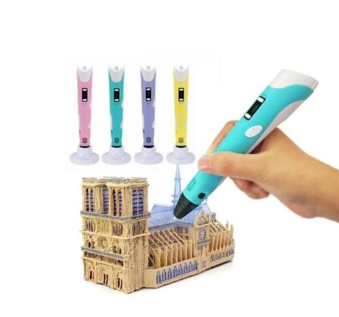
By using the 3D pen can actually help kids developing their artistic skills, spatial thinking, and can be a great creative outlet that engages their minds as they create. Besides, this 3D printing pen has a stable performance. It is more stable, safe and reassuring. Let your child fall in love with 3D printing.
Specifications
- Electrical Parameter: 12VDC 2A
- Comes with UK Plug, Universal (AC voltage and frequency) Adapter
- Can be used everywhere
- 3D printer for hand use
- Compatible with ABS and PLA filaments
- Diameter of filaments: 1.75mm
- Nozzle diameter: 0.7mm
- Heating Temperature:
- 160ºC - 210ºC (PLA)
- 210ºC - 235ºC (ABS)
- LCD for display filament type and temperature
- Adjustable filament feeding speed
- Ergonomic design, lightweight design, easy to operate
- Dimensions: 184mm x 31mm x 46mm
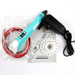
What's in the box ?
1 x 3D Printing Pen with PLA filament - Blu
1 x 3D Printing Pen stand
1 x UK Plug 12V 2A AdapterPLA
1 x Packet filament (3 random colors, 3 meters in total)
1 x User Manual/Operation Instruction
Resources
Want to print a spool holder that clips onto your 3D pen?
Check out Thingiverse
This device allows you to store and use lengths of 1.75mm filament for a 3D pen. The unique mini spool is designed to prevent the filament from unraveling under its own spring tension. The parts can be welded together with your 3D pen.
Check this link out to see what some people come up with :
3D printing pen


Develop your coding skills with the Kitronik :MOVE Motor for micro:bit, a fun introduction to buggies and robotics.
The Kitronik :MOVE Motor for the BBC micro:bit provides a fun introduction to buggy robotics. More than just a programmable buggy, learning to use all of the included features will give the budding roboteer a solid grounding in robotics as a whole.
Learn about movement, how to utilise light and sound, obstacle detection and avoidance, and how to code :MOVE Motor to follow a line. When used in conjunction with the micro:bit's radio features, the possibilities are endless.
Attached to the chassis are two bi-directional DC motors with variable speed control. The wheels have rubber tyres and are a simple push-fit onto the motor shafts. Slot a BBC micro:bit into the edge connector and you are ready to code. There is no other assembly required and no tools required.
There are built-in battery holders for 4x AA batteries. This provides a regulated voltage supply to power the BBC micro:bit which is fed into the edge connector. There is also a power switch to conserve batteries when the buggy is not in use.
The micro:bit slots into the onboard edge connector. Code the micro:bit, plug it into the buggy, switch the power on, and then play.
CODE IT !
:MOVE Motor can be coded using the Microsoft MakeCode editor. Kitronik has produced a set of custom MakeCode blocks to simplify coding the completed buggy. The booklet that comes with the buggy contains more detailed instructions on using the blocks and writing code. If you are feeling more adventurous or relish a challenge, :MOVE Motor can also be coded with Python.
Also within the booklet (that comes inside the box), are some quick tutorials to get you started. There are also additional online tutorials and step by step guides for extra projects.
Note:
- This kit does not include a micro:bit, a micro:bit can be obtained from here.
- No soldering is required!
- Minimal assembly required.

Specifications
| Length | 110mm. |
| Width | 90mm. |
| Voltage | Nominal 4.8 - 6V (4xAA batteries). |
| Motors | Pins 19 and 20 (via I2C). |
| Audio Buzzer | Pin 0 (Standard Music Pin). |
| Visual (4x ZIP LEDs) | Pin 8. |
| Line Follow (IR) | Pins 1 (Right) and 2 (Left). |
| Ultrasonic | Pins 13 (Trigger) and 14 (Echo). |
| Servo Connections | 2 on Pins 15 & 16. |
Features
- The Kitronik :MOVE Motor for the BBC micro:bit provides a fun introduction to buggy robotics and coding.
- It is backed up by a range of fun tutorials to introduce you to all of the great features.
- All of the tutorials and resources are free.
- There is no soldering required and assembly is quick and super simple.
- The buggy features two bi-direction DC motors.
- There are ultrasonic distance and line following sensors onboard.
- It also features a Piezo sounder and pen mount.
- There are 4 full-colour programable ZIP LEDs.
- Two pin outputs that are ideal for servo connections (can be used for other inputs and outputs).
- The battery holder is built onto the chassis.
- The buggy is also fitted with a power switch to conserve the batteries.
- There is also an onboard edge connector for the micro:bit, code, plug and play.
- Kitronik has produced custom MakeCode blocks to simplify coding with the MakeCode editor.
- You can also optionally add a pen for drawing or a robot claw
What's in the box?
1 x :MOVE Motor chassis.
2 x Wheel and tyres.
1 x Booklet
You will also need....
1 x micro:bit
4 x AA batteries
1 x micro USB cable(to program the :MOVE)
Resources

The FLIRC Raspberry Pi Zero Case is finally here - overly engineered, affordable and adorable!
The FLIRC Zero shares the same genetics as the original FLIRC case with some added features. FLIRC have kept everything that makes the original case great, shrunk it down, and added some nice elements that make this mini PC for every day carry.
The familiar aluminium casing with a core heatsink and smooth top is there, offering silent, passive and efficient cooling combined with great looks.
The SD Card is enclosed inside the case so it won't slip out or get stolen. The case needs to be disassembled before the SD card can be removed. There’s even a pre-installed lanyard included in the box in case you want to take your Zero somewhere other than the home.
Two top covers are included with the FLIRC Zero – allowing you to hide away and protect your GPIO, or leave it exposed for prototyping your projects. You can even add a pHAT without worrying about your Zero’s temperature.
What's in the box?
1 x FLIRC Zero Aluminum Case
1 x Thermal pad
2 x Top covers (sealed and GPIO access)
1 x Lanyard (pre-installed, removable)
Notes
1. The Raspberry Pi Zero’s LEDs are not visible with this case
2. Lanyard is removable (but fiddly to get back on)
3. Ships with a thermal pad – fit this to the case heatsink core before fitting your Raspberry Pi Zero
Which Pi Zero Models is the case compatible with?
The case will work with any Raspberry Pi Zero model, including the Raspberry Pi Zero 2 W


The Kitronik LAB:bit for the BBC micro:bit offers a super fun way for children to learn about coding in an engaging and hands-on way. It has been specifically designed for the classroom for KS2 computing and is backed by online MakeCode tutorials, simplified custom blocks, and a detailed getting started guide. Supplied in the box are; a battery holder (3 x AA), a wheel and tyre for the motor, and the detailed easy to follow guide.
The board is absolutely packed with an impressive array of features and devices for easy delivery of fun and informative lessons. These include; a motor, ultrasonic distance sensor, 2 x large user-assignable tactile buttons (with indicator LEDs), a microphone, speaker (with volume control), 7 programmable ZIP LEDs(in an arc), A user-assignable potentiometer control, 2 x sets of traffic light LEDs, and LEDs arranged in a dice formation (that can also be used for displaying digits).
The board also features; an edge connector for the micro:bit to slot into, a pre-fitted protective acrylic cover, clip-able pads for attaching an additional motor, 2 x clip-able pads for attaching further buttons/switches, Colour changing power indication LEDS, a cutaway for easy reset button access, and pre-fitted anti-slip rubber feet.
This all in one laboratory environment ships with a detailed getting started guide, filled with step by step information that can easily be followed by either teacher or pupil. The guide starts with an introduction to using a micro:bit and the MakeCode editor, with each explained in detail. This is then followed by instructions for fitting the wheel to the motor. Each area of the board is explained in detail, complete with code examples for each. As with the previous sections, this part of the booklet has been designed so that it can be used by teachers and pupils.
Coding is done via the MakeCode blocks editor. Kitronik has produced custom blocks for the editor to ensure that they are suitable for use with pupils aged 7-10. Each area of the board has its own blocks that all slot together in intuitive ways and they have been organised into subdirectories by type. For example, all of the blocks for the motor are in one submenu and blocks for the traffic lights are in another submenu. There is also an 'other' submenu that contains blocks for the more advanced/older students who require an extra level of challenge. Detailed information on how to add these blocks to MakeCode can be found in the Getting start guide that ships with LAB:bit.
Power is provided via the provided 3 x AA battery holder into the DC barrel jack input. The board has been rated for a maximum of 6V and a minimum of 3V, 3V - 4.5V recommended. The onboard power regulation circuit provides power to the board and to the micro:bit, removing the need to power the micro:bit separately. LAB:bit has an inbuilt polarity protection circuit for the DC input. There is a Colour changing power LED to indicate when the battery voltage is getting low.
- No soldering.
- Minimal mechanical assembly required. The wheel needs to have the tyre fitted and then to be fitted to the onboard motor.
- This kit is not supplied with a micro:bit. The micro:bit is available separately here.

Features:
- LAB:bit is an all in one educational platform designed for the delivery of KS2 computing in the classroom (7 - 10-year-olds).
- It's packed full of devices, LEDs, switches, sensors, and other programmable features.
- It features an edge connector for the micro:bit to slot into, no tools required.
- LAB:bit is supplied with a pre-fitted protective acrylic cover.
- Additionally, there are clip-able pads for attaching an additional motor, 2 x clip-able pads for attaching further buttons/switches, colour changing power indication LEDs, and a cutaway for easy reset button access.
- There are also pre-fitted anti-slip rubber feet to ensure that LAB:bit stays securely on the desk.
- Code it with blocks in the MakeCode editor.
- Kitronik custom blocks to make coding more intuitive and straightforward.
- Custom blocks are grouped by type to make it easy to go straight to the blocks you need.
- No soldering!
- Minimal mechanical assembly required.
- Supplied in the box are; a battery holder (3 x AA) and a wheel and tyre for the motor.
- Power LAB:bit via the provided 3 x AA battery holder.
- The board is rated for 3V - 6V.
- It has an inbuilt polarity protection circuit for the DC input.
- The onboard power regulation circuit provides power to the board and to the micro:bit, removing the need to power the micro:bit separately.
- LAB:bit is supplied with a fully comprehensive getting started guide. It takes you through everything you need to know and can be followed by both teacher and pupils.
What's in the box ?
1 x Kitronik LAB:bit for the BBC micro:bit
1 x Yellow 5 spoke injection moulded wheel and rubber tyre.
1 x 3AA battery holder.
(* Micro:bit NOT Included *)
Requires the following :
- micro:bit
- USB cable for connecting the micro:bit to a computer.
- 3 x AA Batteries.
- Optional - 5V USB Power Supply (1A or more).
- 7 online MakeCode experiments that teach you how to create code for each area of the board, they are.
- A Pirate ship for LAB:bit.
- Tech Talks - live stream playback.
- Insight Resources Mr Bit:
- LAB:bit downloads.
- Tutorial 1: https://youtu.be/3OMRCZJM5pc
- Tutorial 2: https://youtu.be/xndCctCDCdQ
- Tutorial 3: https://youtu.be/WyJ5bMPAGfg
- Tutorial 4: https://youtu.be/E7jYcPik43Y
- Tutorial 5: https://youtu.be/5pPr_XRS1cE
- Tutorial 6: https://youtu.be/5BDvlVw3M44
- Tutorial 7: https://youtu.be/6v39f_EWGcs
- Projects: https://youtu.be/fQBEHESlxQc
- Download Mr Bit,

(* Micro:bit NOT Included *)