
Pimoroni


A spacious 2.0" (320 x 240) IPS LCD display for Raspberry Pi Pico, with four buttons, an RGB LED and plenty of room for your Pico projects!
This 18-bit capable 320x240 pixel IPS display adheres majestically to the back of your Pico, and has lush colours and great viewing angles. Just like our smaller Display Pack, we've surrounded it with four tactile buttons so you can use your human fingers (or other non-human appendages) to interface with your Pico. There's also an RGB LED that you can use as an indicator, for notifications or just for adding extra rainbows.
Pico Display 2.0 lets you turn a Pico into a user interface device for a bigger project, capable of giving instructions, displaying readouts and even incorporating elaborate nested menus. If you'd rather use your Pico as a standalone device you could fill up all that prime screen real estate with digitally generated, Mandelbrot-esque art, beautiful graphs or readouts from lots of sensors. You could even make a device for getting folks to share their secrets via Telnet!
A Raspberry Pi Pico is not included - click here if you'd like to buy one!
Your Pico will need to have male headers soldered to it (with the pins pointing downwards) to attach to our add-on boards.
- 2.0” 320x240 pixel IPS LCD screen (~220 PPI, 65K colours)
- 4 x tactile buttons
- RGB LED
- Pre-soldered female headers for attaching to Pico
- Compatible with Raspberry Pi Pico.
- Fully assembled
- No soldering required (as long as your Pico has header pins attached).
- Dimensions: approx 56mm x 35mm x 11mm (L x W x H, includes display)
- Screen usable area: 40.8mm x 30.6mm (L x W)
- C/C and MicroPython libraries
- Schematic
About Raspberry Pi Pico
Raspberry Pi Pico is a flexible, low cost microcontroller development board from the folks at Raspberry Pi, based on their very own chip - the RP2040. It's easily programmable over USB with C/C or MicroPython, and ideal for using in all sorts of physical computing projects, devices and inventions - we're so excited to see what you make with it!
We've called our Pico-sized add-ons packs, as they're designed to attach to the back of your Pico as if it were wearing a very stylish back pack (or a miniature jet pack, if you prefer). We've also got Pico bases (larger add-on boards with a space to mount your Pico on top) and some other boards that let you do interesting hackerly things like using multiple packs at once - click here to view them all!
What's in the box ?
1 x Raspberry Pi Pico display (320 x 240) IPS LCD
Resources
Getting started
The labels on the underside of Pico Display will show you which way round to plug it into your Pico - just match up the USB port with the markings on the board.
The easiest way to get started is by downloading and copying our custom MicroPython uf2 to your Pico, it includes all the libraries you'll need to use our add-ons. Click here for our beginner friendly tutorial!
You can find C examples here and MicroPython examples here. You can also use it with CircuitPython!
Notes
- This screen is a wee bit taller than the surrounding buttons, so it's worth taking care when pressing the buttons that you're not also pressing down on the screen, particularly at the edge with the ribbon cable. Careful pressing with fingertips rather than full on thumb mashing is the way forward!
- Even though it's bigger than our other Pico Packs, Display 2.0 will still work with Pico Omnibus or Pico Decker, if you want to use more than one Pico Pack at once. Please note that if you plug Display 2.0 into a Pico Decker, it will overhang the addon slot next to it.


Six touch-sensitive buttons to use for whatever your heart desires, with added LEDs (did you expect anything less?)
Touch pHAT has six capacitive touch buttons, each with a bright white LED, designed to be completely agnostic about what they're used for. You can even use a dry erase pen to write on the pads to label their function.
It uses the CAP1166 capacitive touch and LED driver chip. The LEDs have been under-mounted and shine through exposed sections of the PCB to give a pleasing yellow-green glow and a completely smooth top surface!
Use Touch pHAT as a controller for your robot, a controller for your Mote lights, a tiny drum machine, or use it to build a simple game where you have to taps the buttons to repeat the sequence of lights that just flashed.
Features
- Six capacitive touch buttons
- Six bright white under-mounted LEDs
- Microchip CAP1166 capacitive touch and LED driver chip
- Compatible with Raspberry Pi 3, 2, B , A , Zero, Zero W
- Python library
- Female header requires soldering
Software
Our handy one-line installer will install the Touch pHAT Python library for you. We've included a couple of examples too, to show off what you can do with Touch pHAT.
Protect your Pi Zero 2 W in style with the Pibow Zero 2 W case, in calming violet waters - ocean blue, purple, and deep blue!
Note: this case is for the Raspberry Pi Zero 2 W only. This case is not compatible with the Pi Zero or the original Pi Zero W. Does not include a Raspberry Pi Zero 2 W!
We've got a tutorial showing you how to build your Pibow here.
Features
- Compatible with Raspberry Pi Zero 2 W
- Super-slimline profile
- Fully HAT/pHAT compatible
- Protects your beloved Pi Zero 2 W!
- Clear top leaves Raspberry Pi Zero 2 W visible
- GPIO cut-out
- Leaves ports and GPIO accessible (encloses micro SD)
- Slot for camera cable to slip between layers
- Made from lightweight high-quality cast acrylic
- Great for hacking and tinkering!
- Made in Sheffield, UK
Crafted out of four unique layers including a transparent top and base that leave your beautiful Pi visible inside. Each layer is laser-cut from colourful high-quality cast acrylic and once stacked they securely contain a Raspberry Pi Zero 2 W while leaving the primary ports and GPIO accessible.
This case is lightweight and ideal for mounting to any surface. No tools are required for assembly or disassembly!
What's in the box?
1 x Pibow case for Zero 2 W

A meteorologically minded Raspberry Pi HAT designed to make hooking up weather sensors a breeze (or a squall, or a gale).
Weather HAT is a tidy all-in-one solution for hooking up climate and environmental sensors to a Raspberry Pi. It has a bright 1.54" LCD screen and four buttons for inputs. The onboard sensors can measure temperature, humidity, pressure and light. The sturdy RJ11 connectors (remember those?) will let you easily attach wind and rain sensors. It will work with any Raspberry Pi with a 40 pin header (that's most of them except the really old ones).
You could install it outside in a suitable weatherproof enclosure (like a waterproof junction box or even a Tupperware container) and connect to it wirelessly - logging the data locally or piping it into Weather Underground, a MQTT broker or a cloud service like Adafruit IO. Alternatively, you could house your weather Pi inside and run wires to your weather sensors outside - making use of the nice screen to display readouts.
Please note: the wind and rain sensors are sold separately.
Features
- 1.54" IPS LCD screen (240 x 240)
- Four user-controllable switches
- BME280 temperature, pressure, humidity sensor (datasheet)
- LTR-559 light and proximity sensor (datasheet)
- Nuvoton MS51 microcontroller with inbuilt 12-bit ADC (datasheet)
- RJ11 connectors for connecting wind and rain sensors (sold separately)
- HAT-format board
- Fully-assembled
- Compatible with all 40-pin header Raspberry Pi models
- Python library
- Schematic
What's in the box?
1 x Weather HAT
2 x 10mm standoffs
Raspberry Pi and accessories are sold separately
Software
We've put together a Python library to give you easy access to all Weather HAT's functions, together with straightforward examples to help you learn how to read the sensors and use all the individual parts. There's also a weather station example that shows you how it's possible to combine all the functions into an application.
Our Getting Started tutorial contains a thorough walkthrough of Weather HAT's functionality plus beginner friendly instructions for installing the Python library and running the examples.
Notes
- Want to add on more I2C sensors? No problem, there's an solderless I2C header located on the back of the HAT that you can poke jumper / DuPont wires in to.
- If you'd like to hook up more analog sensors (3.3v max) we've broken out some extra ADC channels on the front of the board, as well as a convenient 3v3 power and ground.
- We've found two standoffs at the GPIO edge to be sufficient to keep this HAT firmly in place, but if you're attaching it to a full-size Pi and want to add standoffs at every corner you can pick up some more.
- Dimensions: 65 x 56.5 x 19 mm (L x W x H, including header and connectors)

A wireless climate and environmental monitoring system designed to make hooking up weather sensors a breeze (or a squall, or a gale).
Enviro Weather is a super slimline all in one board for keeping a (weather) eye on the great outdoors. The onboard sensors can measure temperature, humidity, pressure and light. The sturdy RJ11 connectors (remember those?) will let you easily attach wind and rain sensors. We've designed this one to be installed outside in a suitable weatherproof enclosure (like a Stevenson screen) and connected to wirelessly - logging the data locally or piping it into databases, home automation dashboards or online citizen science projects.
Please note wind and rain sensors are sold separately.
Enviro x Pico W Aboard
Our new Enviro (Pico W Aboard) range is designed with environmental monitoring / logging in mind. We wanted to make a range of Pico/RP2040-powered, all-in-one sensor boards that are compact, easy to install in places and straightforward to program. The wireless capability of Raspberry Pi Pico W lets Enviro integrate with other systems - so you could post your data into databases, home automation systems, or online citizen science efforts - the Internet's your lobster!
Because the least fun thing about adding lots of sensors to your environment is figuring out how supply power to everything without tons of trailing wires, they are all designed to work well off battery power. Each Enviro board has an onboard RTC (Real Time Clock), so that they can periodically wake up from deep sleep, take a reading (and, optionally, connect to wifi) and then go back to sleep - giving you months of untethered battery life.
We've also put together some handy accessory kits to go with our Enviro boards, that include an appropriately sized AA or AAA battery pack, a USB cable and other essentials for each board, so you can get going super quick.
Enviro Features
- Raspberry Pi Pico W Aboard
- Dual Arm Cortex M0+ running at up to 133Mhz with 264kB of SRAM
- 2MB of QSPI flash supporting XiP
- Powered and programmable by USB micro-B
- 2.4GHz wireless
- Deep sleep/wake function using RTC
- 1 x POKE (user) button
- Reset button (because we're not monsters)
- Battery connector (JST-PH connector, 5.5V max voltage)
- User/activity LED (dimmable via PWM, can only be lit when board is awake)
- Warn LED (attached to RTC)
- Qw/ST connector for attaching breakouts
- Fully assembled
- No soldering required.
- Enviro firmware
- Schematic
Enviro Weather Features
- BME280 temperature, pressure, humidity sensor (datasheet)
- LTR-559 light and proximity sensor (datasheet)
- RJ11 connectors for connecting wind and rain sensors
What's in the box?
1 x Enviro Weather board (Pico W Aboard)
Software
Enviro ships with some super slick provisioning software that makes it really easy to set it up and connect to things, even if it's your first foray into environmental logging/IoT. Power it up and connect to the network called 'Enviro Weather Setup' with your phone, tablet or other wi-fi enabled device - your Pico W will walk you through the rest!
Connecting Breakouts
The Qw/ST connectors on Enviro boards make it super easy to connect up I2C Qwiic or STEMMA QT breakouts. If your breakout has a QW/ST connector on board, you can plug it straight in with a JST-SH to JST-SH cable.
Breakout Garden breakouts that don't have a Qw/ST connector can be connected using a JST-SH to JST-SH cable plus a Qw/ST to Breakout Garden adaptor.
- List of breakouts currently compatible with our C++/MicroPython build.
Notes
- Measurements: 69 x 36 x 14 mm (L x W x H, approx)
- Enviro boards can enter a deep sleep mode where the Pico W, on board sensors and sensors connected via Qw/ST are completely powered down. The only thing left running on the board is the RTC which can wake up the board again at a set date and time or on a timer. You can also wake up the board via the POKE button, or by connecting the USB cable (the board will never sleep if connected to USB power). Power consumption when asleep is 20uA.
- The RTC can also be used to keep track of the time and date (which means we don't need to waste power by making a wireless call to find out the time/date each time we log a sensor reading!)
- The Warn LED is connected to the RTC, so it can be lit even during deep sleep to notify you of problems. It is limited to three states - on, off, or 1hz blink (it's not possible to control the brightness).
- Most Enviro boards can be powered by a 2 x AAA battery pack, which fits neatly behind the board. Any battery pack that can supply between 2V and 5.5V will work though - 2 or 3 alkaline AA or AAA cells, 4 rechargeable NiMH cells or a single cell LiPo. If you're using a LiPo, bear in mind there's no battery charging included on Enviro boards, so you'll need a separate LiPo battery charger (like a LiPo Amigo) to be able to charge it.
About Pico W Aboard
Our new Pico W Aboard products come with a built in Raspberry Pi Pico W. This means you get all the advantages of a RP2040 microcontroller - a speedy fast dual-core ARM processor, a dynamic, growing ecosystem and a choice of different programming methods to experiment with. Most excitingly though, Pico W has wireless connectivity, so your Pico/RP2040 devices can communicate with each other, and the internet!

A wireless environmental monitoring board to keep track of inside conditions in your home, office or other habitat. Onboard sensors can measure temperature, humidity, pressure, gas and light.
The top of the range BME688 sensor on Enviro Indoor can measure temperature/humidity/pressure with a high degree of precision, and the gas scanner will react to changes in volatile organic compounds (VOCs), volatile sulfur compounds (VSCs) and the presence of carbon monoxide and hydrogen to give a general measure of air quality. The BH1745 light sensor can tell you the luminance and colour of light, so you could use it to detect unrestful blue light or adjust your lighting's intensity/hue depending on the time of day.
Want to add more sensors to this board? A CO2 sensor breakout (plugged into the Qw/ST connector) would make a nice addition, so you could keep an eye on ventilation levels and cognition impairing carbon dioxide build-up.
Enviro x Pico W Aboard
Our new Enviro (Pico W Aboard) range is designed with environmental monitoring / logging in mind. We wanted to make a range of Pico/RP2040-powered, all-in-one sensor boards that are compact, easy to install in places and straightforward to program. The wireless capability of Raspberry Pi Pico W lets Enviro integrate with other systems - so you could post your data into databases, home automation systems, or online citizen science efforts - the Internet's your lobster!
Because the least fun thing about adding lots of sensors to your environment is figuring out how supply power to everything without tons of trailing wires, they are all designed to work well off battery power. Each Enviro board has an onboard RTC (Real Time Clock), so that they can periodically wake up from deep sleep, take a reading (and, optionally, connect to wifi) and then go back to sleep - giving you months of untethered battery life.
We've also put together some handy accessory kits to go with our Enviro boards, that include an appropriately sized AA or AAA battery pack, a USB cable and other essentials for each board, so you can get going super quick.
Enviro Features
- Raspberry Pi Pico W Aboard
- Dual Arm Cortex M0+ running at up to 133Mhz with 264kB of SRAM
- 2MB of QSPI flash supporting XiP
- Powered and programmable by USB micro-B
- 2.4GHz wireless
- Deep sleep/wake function using RTC
- 1 x POKE (user) button
- Reset button (because we're not monsters)
- Battery connector (JST-PH connector, 5.5V max voltage)
- User/activity LED (dimmable via PWM, can only be lit when board is awake)
- Warn LED (attached to RTC)
- Qw/ST connector for attaching breakouts
- Fully assembled
- No soldering required.
- Enviro firmware
- Schematic
Enviro Indoor Features
- BME688 4-in-1 temperature, pressure, humidity and gas sensor (datasheet)
- BH1745 light (luminance and colour) sensor (datasheet)
Software
Enviro ships with some super slick provisioning software that makes it really easy to set it up and connect to things, even if it's your first foray into environmental logging/IoT. Power it up and connect to the network called 'Enviro Indoor Setup' with your phone, tablet or other wi-fi enabled device - your Pico W will walk you through the rest!
Connecting Breakouts
The Qw/ST connectors on Enviro boards make it super easy to connect up I2C Qwiic or STEMMA QT breakouts. If your breakout has a QW/ST connector on board, you can plug it straight in with a JST-SH to JST-SH cable.
Breakout Garden breakouts that don't have a Qw/ST connector can be connected using a JST-SH to JST-SH cable plus a Qw/ST to Breakout Garden adaptor.
- List of breakouts currently compatible with our C++/MicroPython build.
Notes
- Measurements: 69 x 36 x 9.9 mm (L x W x H, approx)
- Enviro boards can enter a deep sleep mode where the Pico W, on board sensors and sensors connected via Qw/ST are completely powered down. The only thing left running on the board is the RTC which can wake up the board again at a set date and time or on a timer. You can also wake up the board via the POKE button, or by connecting the USB cable (the board will never sleep if connected to USB power).
- The RTC can also be used to keep track of the time and date (which means we don't need to waste power by making a wireless call to find out the time/date each time we log a sensor reading!)
- The Warn LED is connected to the RTC, so it can be lit even during deep sleep to notify you of problems. It is limited to three states - on, off, or 1hz blink (it's not possible to control the brightness).
- Most Enviro boards can be powered by a 2 x AAA battery pack, which fits neatly behind the board. Any battery pack that can supply between 2V and 5.5V will work though - 2 or 3 alkaline AA or AAA cells, 4 rechargeable NiMH cells or a single cell LiPo. If you're using a LiPo, bear in mind there's no battery charging included on Enviro boards, so you'll need a separate LiPo battery charger (like a LiPo Amigo) to be able to charge it.
About Pico W Aboard
Our new Pico W Aboard products come with a built in Raspberry Pi Pico W. This means you get all the advantages of a RP2040 microcontroller - a speedy fast dual-core ARM processor, a dynamic, growing ecosystem and a choice of different programming methods to experiment with. Most excitingly though, Pico W has wireless connectivity, so your Pico/RP2040 devices can communicate with each other, and the internet!
What's in the box?
1 x Enviro Indoor

Features
- Raspberry Pi Pico W Aboard
- Dual Arm Cortex M0+ running at up to 133Mhz with 264kB of SRAM
- 2MB of QSPI flash supporting XiP
- Powered and programmable by USB micro-B
- 2.4GHz wireless
- Compatible with 5V WS2812/Neopixel/SK6812 LEDs
- Screw terminals for attaching your LED strip.
- Reset button
- Qw/ST (Qwiic/STEMMA QT) connector
- Fully-assembled (no soldering required)
- C++/MicroPython libraries
- Schematic
LED strip and connectors are sold separately, check out the extras tab for some options!
What's in the box?
1 x Plasma Stick 2040 W
Software
You can program Pico/RP2040 boards in a bunch of different ways, but if you're a beginner we'd recommend using our batteries included MicroPython build for ease of getting started. We've pre-loaded Plasma Stick with pirate-brand MicroPython and some fun examples to help you get started.
- (Learn) Getting Started with Raspberry Pi Pico
- (Learn) Assembling Wireless Plasma Kit
- Download pirate-brand MicroPython (you'll need the `picow` .uf2)
- MicroPython examples
- MicroPython function reference
- C++ examples
Alternatively, you could install CircuitPython on your Pico W! CircuitPython is an easy to use, well-established ecosystem with lots of example code and drivers for interfacing with different kinds of hardware - and it's just got Pico W wireless support, woop!
- Download CircuitPython for Plasma 2040
- Welcome to CircuitPython
- CircuitPython examples
- Quick-Start the Pico W WiFi with CircuitPython
If you're adapting examples from elsewhere and need to know the pins that Plasma Stick uses, it's GP15 for LED data, GP4 for I2C SDA and GP5 for I2C SCL.
You might also need one of our tested 128GB, 256GB or 512GB NVMe drives or a clear acrylic case to protect your RPi5 and NVMe Base.
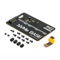
NVMe Base is a PCIe extension board for Raspberry Pi 5. Simply populate it with an M-key NVMe SSD (2230 to 2280 sizes supported) and mount it under your Pi for a compact and fast storage solution - It even comes with rubber feet!
It's the perfect solution for turning your Raspberry Pi 5 into a file server, media centre, reverse proxy, etc. - really any task that benefits from large amounts of fast storage, especially with random high operations per second (IOPS) workloads. In short it's a game changer!
NVMe base follows the new "PIP" design guidelines provided by Raspberry Pi ensuring that it will be easy to use and be supported long term by updates to Raspberry Pi OS - though it is very early days and things are improving rapidly there!
What's in the box?
1 x NVMe Base PCB with M.2 Slot (M-Key)
1 x 'PCIe Pipe' Flat Flex Cable
4 x Rubber feet
1 x M2 bolt and 2x nuts for SSD mounting
4 x 7mm M2.5 standoffs for base mounting
8 x short M2.5 bolts for base mounting
4 x long M2.5 bolts for 'pass-thru' mounting with a HAT
You might also need a NVMe drive. Make sure you choose one that fits your NVMe board.
Driver compatibility
We have tested NVMe Base with the following M.2 NVMe drives successfully. We have usually tested one drive from one batch, so this is not comprehensive, or an 'Approved' list, but it's a good guide for drives to seek out:
- AData Legend 700
- AData Legend 800
- AData XPG SX8200 Pro
- Axe Memory Generic Drive
- Crucial P2 M.2
- Crucial P3 M.2
- Crucial P3 Plus M.2
- Inland PCIe NVMe SSD
- Kingston KC3000
- Kioxia Exceria NVMe SSD
- Kioxia Exceria G2 NVMe SSD
- Lexar NM620
- Lexar NM710
- Netac NV2000 NVMe SSD
- Netac NV3000 NVMe SSD
- Origin Inception TLC830 Pro NVMe
- PNY CS1030
- Sabrent Rocket 4.0
- Sabrent Rocket Nano
- Samsung 980
- Samsung 980 Pro (500GB/1TB)
- Team MP33
- Western Digital Black SN750 SE (Phison Controller
' Maybe' List. Works with quirks/not ideal.
These drives either needed extra power, were a bit quirky when we tested them or we've had reports of them being problematic. It may just be the drive we had, but they're probably best avoided.
- Kioxia BG4 2230. Performance very patchy. Runs at quite a high temp.
- Patriot P300 - These drives have various controllers, some of which seem to be incompatible at this time.
- Patriot P310 - These drives have various controllers, some of which seem to be incompatible at this time.
- Samsung 970 EVO Plus. Runs at a higher temp. Some user reports of problems under heavy load or not showing up on boot.
- Samsung 980 Pro (250GB). Reports of this size not working.
- WD Blue SN550. Our fresh unit could be used as storage but could not be booted from.
- WD Red SN700. Slow to boot first time, but worked and booted OK.
- WD SN740. Our fresh unit worked well. YMMV.
- WD Black SN770. Our fresh unit worked fine. YMMV.
- Patriot P300. All units we've tested work but we have heard of a 256GB/1TB variant that doesn't.
'Avoid' List. We've had problems or reports of problems.
- Transcend 110Q (TS500GMTE110Q)
- WD Green/Blue/Red/Black not in the above list. Variable results or not working because of quirks of a SanDisk controller/firmware. Our SN350 and SN570 prevented the RPi 5 from booting at all especially.
Otherwise most M.2 NVMe drive (Not SATA!) you have lying around should work fine.
Check out our benchmark results over at pibenchmarks.net!
Resources
- Video: Installing the Pimoroni NVMe Base on Raspberry Pi 5 ????
- Learn: Getting Started with NVMe Base for Raspberry Pi 5 ????
Firmware
For the most hassle-free experience, make sure your Raspberry Pi OS is up to date, and your RPi 5 firmware is updated to 2023-12-06 (Dec 6th) or newer. This supports all the features of the RPi PCIe spec and means you don't have to mess with config files to get started.
Software update on the RPi OS should do this for you, but to force it you can:
- open a Terminal (Ctrl-Alt-T)
- run
sudo raspi-configand choose 'Latest' under Advanced Options > Bootloader Version.
Running sudo rpi-eeprom-update in the Terminal will tell you which version of firmware is running.
PCIe 3 Mode
To enable experimental and not-officially-supported PCIe 3 mode, add the follow line to the [all] section at the end of your Raspberry Pi /boot/firmware/config.txt file like this:
[all]
dtparam=pciex1_gen=3
Save and reboot - your drive is ready to use!
Formatting the NVMe and booting from NVMe
If you want to boot from the NVMe drive, follow these extra steps:
- Make sure your firmware is updated as above!
- Format the drive using Raspberry Pi Imager
- You can do this with your NVMe Base installed by booting the RPi 5 from SD card and running Raspberry Pi Imager from the start menu.
- Open a Terminal (Ctrl-Alt-T).
- Run
sudo raspi-config - Choose NVMe/USB boot under Advanced Options > Boot Order.
- Reboot your RPi 5.
Notes
- Always power off your RPi and disconnect the power supply before installing or uninstalling the NVMe Base.
- NVMe Base offers a general purpose PCIe x1 connection - while we know most people want to add fast storage in theory you can use other devices with it, we just can't help you make them work! :-D What Would Jeff (Geerling) Do?

Monitor your world with Enviro for Raspberry Pi! There's a whole bunch of fancy environmental sensors on this board, and a gorgeous little full-colour LCD to display your data. It's the perfect way to get started with citizen science!
Designed for environmental monitoring, Enviro lets you measure air quality (pollutant gases and particulates*), temperature, pressure, humidity, light, and noise level. When combined with a particulate matter sensor*(not included), it's great for monitoring air quality just outside your house (more information below), or without the particulate sensor you can use it to monitor indoor conditions.
Enviro is an affordable alternative to environmental monitoring stations that can cost tens of thousands of pounds and, best of all, it's small and hackable and lets you contribute your data to citizen science efforts to monitor air quality via projects like Luftdaten.
Features
- BME280 temperature, pressure, humidity sensor (datasheet)
- LTR-559 light and proximity sensor (datasheet)
- MICS6814 analog gas sensor (datasheet)
- ADS1015 analog to digital converter (ADC) (datasheet)
- MEMS microphone (datasheet)
- 0.96" colour LCD (160x80)
- Connector only for particulate matter (PM) sensor*(sensor is included)
- pHAT-format board
- Fully-assembled
- Compatible with all 40-pin header Raspberry Pi models
- Pinout
- Python library
- Dimensions: 65x30x8.5mm
A couple of nice little extras... there's a spare ADC channel broken out on a header if you want to connect another analog sensor, along with I2C pins in the right configuration for plugging one of our Pimoroni I2C breakouts onto!
Citizen science air quality monitoring
We've developed this board in collaboration with the University of Sheffield, with the aim of letting you contribute real-time air quality data from your local area to open data projects like Luftdaten.
The alarming drop in our air quality is something that's really important to understand. Devices like Enviro allow fine-grained, detailed datasets that let us see shifts in air quality through time and across different areas of cities. The more devices that contribute data, the better quality the dataset becomes.
Particulate matter (PM) is made up of tiny particles that are a mix of sizes and types, like dust, pollen, mould spores, smoke particles, organic particles and metal ions, and more. Particulates are much of what we think of as air pollution. They can be measured, in size and quantity, by particulate matter sensors like the PMS5003 that you can connect to Enviro .
The analog gas sensor can be used to make qualitative measurements of changes in gas concentrations, so you can tell broadly if the three groups of gases are increasing or decreasing in abundance. Without laboratory conditions or calibration, you won't be able to say "the concentration of carbon monoxide is n parts per million", for example.
Temperature, air pressure and humidity can all affect particulate levels (and the gas sensor readings) too, so the BME280 sensor on Enviro is really important to understanding the other data that Enviro outputs.
We've got a tutorial (coming soon) that shows you how to use Enviro and a few easily-available bits to build the board into a weather-proof housing that you can mount outside your house to monitor local air quality.
Indoor monitoring
As well as outdoor air quality monitoring, Enviro is really good for indoor monitoring too. The temperature, humidity, light, and noise readings can be used to keep track of conditions in your home and, combined with the LCD to display the data and the proximity sensor for interaction, it makes an ideal headless monitoring device.
Why not combine it with some IoT smarts like an Alexa skill so that you can ask what the temperature or humidity is? Or you could set up a trigger action with IFTTT that turns your Philips Hue lights on when the light level drops below a certain level. There's loads of possibilities!
What's in the box?
1 x Enviro board
1 x air quality sensor pre-soldered on the Enviro board
Resources
Software
We've put together a Python library to control all the parts of your Enviro . There's a bunch of examples for each of the individual parts, an all-in-one example that shows you the data from Enviro 's sensors in a visual way. There's also an example that shows you how to contribute data to Luftdaten (requires particulate matter sensor).
Getting started
Have a read through our (exhaustive!) Getting Started with Enviro tutorial that walks you through how to install the software, how to run the code examples, and how to use the Enviro Python library.
You might also need one of our tested 128GB, 256GB or 512GB NVMe drives or a clear acrylic case to protect your RPi5 and NVMe Base.
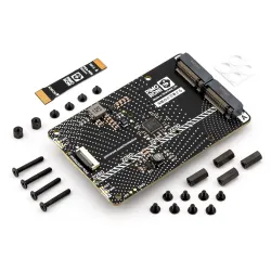
NVMe Base Duo is a PCIe Gen 2 extension board for Raspberry Pi 5. Simply populate it with one or two M-key NVMe SSDs (2230 to 2280 sizes supported) and mount it under (or over) your Pi for a compact and fast storage solution - It even comes with rubber feet!
It's the perfect solution for turning your Raspberry Pi 5 into a file server, media centre, reverse proxy, etc. - really any task that benefits from large amounts of fast storage, redundancy, or just to make use of a couple of spare disk - especially with random high operations per second (IOPS) workloads. In short it's a game changer!
NVMe Base Duo follows the new "PIP" design guidelines provided by Raspberry Pi ensuring that it will be easy to use and be supported long term by updates to Raspberry Pi OS - though it is very early days and things are improving rapidly there!
What's in the box?
1 x NVMe Duo Base PCB with M.2 Slot (M-Key)
1 x cable and bolts kit
You might also need a NVMe drive.
NOTE: You can only boot from the NVME drives if your Raspberry Pi firmware is updated to the most recent version (17/05/24 or later).
NOTE: The shipping product may have minor differences to the photos, but will be the same in essentials.
Raspberry Pi Firmware
For the most hassle-free experience, make sure your Raspberry Pi OS is up to date, and your RPi 5 firmware is updated to 2023-12-06 (Dec 6th) or newer. This supports all the features of the RPi PCIe spec and means you don't have to mess with config files to get started.
Base Kit
- NVMe Base Duo PCB with two M.2 slots (M-Key)
- 'PCIe Flex' Flat Flex Cable
- 4x Rubber feet
- 4x M2 bolt and 2x 5mm standoffs for SSD mounting
- 4x 12mm M2.5 standoffs for base mounting
- 8x short M2.5 bolts for base mounting
- 4x 20mm M2.5 bolts for 'pass-thru' mounting with a HAT
NVMe Base Duo + 500GB (2 x 250GB) SSD Bundle
The Base Kit bundled with 2 x 250GB+ NVMe SSDs (PCIe Gen 3 or better, although this Base only supports Gen 2 speeds).
NVMe Base Duo + 1000GB (2 x 500GB) SSD Bundle
The Base Kit bundled with 2 x 500GB+ NVMe SSDs (PCIe Gen 3 or better, although this Base only supports Gen 2 speeds).
We recommend running the Raspberry Pi 5 at PCIe Gen 2 x 1 speeds with this Base. The total throughput is around 450MB/sec, or 220MB/sec+ per disk for simultaneous access as they share the bandwidth through the PCIe Switch.
Due to the tides and vagueries of the SSD market, we will ship whichever drive offers the best value for decent specs. We can say that:
- It will have 250/500GB or better capacity
- It will be rated by the manufacturer at PCIe Gen 3 or better speed
- We'll have personally tested the drive with the NVMe Base and it will be in the list below.
- It'll be backed by the usual Pimoroni guarantees and customer service.
SSD testing with the NVMe Base Duo is underway, in the meanwhile here is a list of drives tested with the single-drive NVMe Base.
We have usually tested one drive from one batch, so this is not comprehensive, or an 'Approved' list, but it's a good guide for drives to seek out:
- AData Legend 700
- AData Legend 800
- AData XPG SX8200 Pro
- Axe Memory Generic Drive
- Crucial P2 M.2
- Crucial P3 M.2
- Crucial P3 Plus M.2
- Inland PCIe NVMe SSD
- Kingston KC3000
- Kioxia Exceria NVMe SSD
- Kioxia Exceria G2 NVMe SSD
- Lexar NM620
- Lexar NM710
- Netac NV2000 NVMe SSD
- Netac NV3000 NVMe SSD
- Origin Inception TLC830 Pro NVMe
- PNY CS1030
- Sabrent Rocket 4.0
- Sabrent Rocket Nano
- Samsung 980
- Samsung 980 Pro (500GB/1TB)
- Team MP33
- Western Digital Black SN750 SE (Phison Controller)
' Maybe' List. Works with quirks/not ideal.
These drives either needed extra power, were a bit quirky when we tested them or we've had reports of them being problematic. It may just be the drive we had, but they're probably best avoided.
- Kioxia BG4 2230. Performance very patchy. Runs at quite a high temp.
- Patriot P300 - These drives have various controllers, some of which seem to be incompatible at this time.
- Patriot P310 - These drives have various controllers, some of which seem to be incompatible at this time.
- Samsung 970 EVO Plus. Runs at a higher temp. Some user reports of problems under heavy load or not showing up on boot.
- Samsung 980 Pro (250GB). Reports of this size not working.
- WD Blue SN550. Our fresh unit could be used as storage but could not be booted from.
- WD Red SN700. Slow to boot first time, but worked and booted OK.
- WD SN740. Our fresh unit worked well. YMMV.
- WD Black SN770. Our fresh unit worked fine. YMMV.
- Patriot P300. All units we've tested work but we have heard of a 256GB/1TB variant that doesn't.
'Avoid' List. We've had problems or reports of problems.
- Transcend 110Q (TS500GMTE110Q)
- WD Green/Blue/Red/Black not in the above list. Variable results or not working because of quirks of a SanDisk controller/firmware. Our SN350 and SN570 prevented the RPi 5 from booting at all especially.
Otherwise most M.2 NVMe drive (Not SATA!) you have lying around should work fine.
Check out our benchmark results over at pibenchmarks.net!
NOTE: Drives may be from the same manufacturing batch. If you're a storage-integrity aficionado, you may want to source your own drives to avoid the unlikely edge-case of an issue or bug affecting an entire batch of drives.
Getting started
Firmware
Make sure your Raspberry Pi OS and RPi 5 firmware are up to date and newer than December 2023. Software update on the RPi OS should do this for you, but you can force it by starting a Terminal and running sudo raspi-config and choosing 'latest' under firmware options, then running sudo rpi-eeprom-update in the Terminal. This will also tell you which firmware is running.
Notes
- Always power off your RPi and disconnect the power supply before installing or uninstalling the NVMe Base.
- You cannot, at this time, boot from the drives installed on the NVM Base Duo. The single NVMe Base does support booting from the NVMe.
- NVMe Base Duo offers offers two PCIe Gen 2 M.2 slots behind a PCIe Gen2 Packet Switcher on a general purpose PCIe x1 connection - while we know most people want to add fast storage in theory you can use other devices with it, we just can't help you make them work! :-D What Would Jeff (Geerling) Do
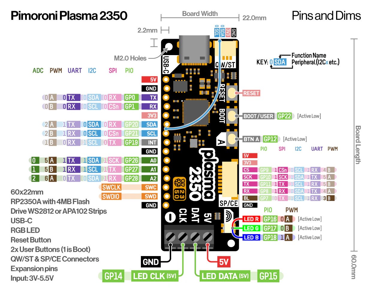
While we love the Raspberry Pi Pico we also wanted something smaller and with a bunch more flash on board. Introducing the Tiny 2350 - a teeny tiny powerhouse with the chops to realise truly ambitious projects.
Programmable via USB-C, Tiny 2350 comes with 4MB of flash storage on board. The board is designed with castellated pads to allow it to be directly soldered onto a PCB (or you can attach pin headers to hook it up on a breadboard or connect things to it directly with wires). We've also managed to fit in a programmable RGB LED, a reset button, a Qw/ST connector for connecting up I2C devices and some clever circuitry that lets you use the boot button as a user controllable switch.
It's compatible with firmware built for the Raspberry Pi Pico 2 but offers a reduced number of pins due to its size. You can even run MicroPython on it!
Features
- Powered by RP2350A (Dual Arm Cortex M33 running at up to 150MHz with 520KB of SRAM)
- 4MB of QSPI flash supporting XiP
- USB-C connector for power, programming, and data transfer
- User controllable RGB LED
- Qw/ST (Qwiic/STEMMA QT) connector for attaching breakouts
- Twelve IO pins (including four 12-bit ADC channels)
- Reset and BOOT buttons (the BOOT button can also be used as a user button)
- On-board 3V3 regulator (max regulator current output 300mA)
- Input voltage range 3V - 5.5V
- Programmable with C/C++ or MicroPython
- Dimensions: approx 22.9 x 18 x 5.8mm (L x W x H, including the USB-C port)
About RP2350
The RP2350 chip is the Double Quarter Pounder & Fries to the RP2040's Double Cheeseburger and can have one or more RISC-V burgers instead of either of the M33 ARMs, to stretch the metaphor.
In addition to the modern M33 ARM cores, there are sides of: more PIO capability, a variety of low power states for sipping electrons, a whole security system and some sprinklings of specialist digital video circuits to offload DVI/HDMI output.
You can expect a tasty boost in performance - our "real world" MicroPython tests are running up to 2x faster compared to RP2040, and floating point number crunching in C/C++ is up to 20x faster. The extra on-chip RAM will make a big difference when performing memory intensive operations (such as working with higher resolution displays) and even more can be added thanks to external PSRAM support.
RP2350 comes in two flavours - A (standard) and B (all the pins). The B chip has a stonking 48 usable GPIO pins, including 8 ADCs and 24 PWMs, and features on some of our new products.
What's in the box?
1 x Tiny 2350 board
Resources
Pinout and Schematic

- Download a printable PDF version
- Schematic (coming soon)
Getting Started
Connecting Breakouts
If your breakout has a Qw/ST connector on board, you can plug it straight in with a JST-SH to JST-SH cable, or you can easily connect any of our I2C breakouts with a JST-SH to JST-SH cable coupled with a Qw/ST to Breakout Garden adaptor.
Notes
- As well as being useful for putting your Tiny 2350 into bootloader mode, you can also use the BOOT button as a user switch. It's wired to GP23 and active low.
- The RGB LED is connected to GP18-GP20 and active low (so the on/off state will work in the opposite way to the LED on a Raspberry Pi Pico). You can PWM the pins to dim the LED - check out Tonygo2's MicroPython example.

An all-in-one, USB-C powered controller for WS2812/Neopixel and APA102/Dotstar addressable LED strips.
Plasma 2350 is powered and programmable by USB-C and, because USB-C is capable of drawing up to 3A of power, that's enough to power a healthy chunk of LEDs. There's a useful button that you could use to switch between effects, plus a reset button and an onboard RGB LED. We've also popped a QW/ST connector on there, to make it super easy to plug in Qwiic or STEMMA QT breakouts.
You can buy a Plasma 2350 on its own, or in a kit with a USB-C cable and some super-cool LED stars, so you can get started lighting stuff up right away.
Features
- Powered by RP2350A (Dual Arm Cortex M33 running at up to 150MHz with 520KB of SRAM)
- 4MB of QSPI flash supporting XiP
- Compatible with 5V WS2812/Neopixel/SK6812 and APA102/Dotstar/SK9822 LEDs
- Screw terminals for attaching your LED strip.
- USB-C connector for power and programming (3A max)
- Qw/ST (Qwiic/STEMMA QT) connector
- Intriguing new SP/CE connector
- Reset, BOOT and a user button (the BOOT button can also be used as a user button)
- RGB LED
- Fully-assembled (no soldering required)
- Measurements: approx 61 x 22 x 12mm (L x W x H, including connectors)
- Programmable with C/C++ or MicroPython
STARter Kit contains
- Plasma 2350
- USB-C cable for power and programming
- 10m RGB LED Star Wire
Pintout and Schematic
- Download a printable PDF version
- Schematic (coming soon)
Getting Started
Connecting Breakouts
If your breakout has a QW/ST connector on board, you can plug it straight in with a JST-SH to JST-SH cable, or you can easily connect any of our I2C breakouts with a JST-SH to JST-SH cable coupled with a Qw/ST to Breakout Garden adaptor.
We've also broken out the I2C, analog, UART and debug pins so you can solder things like breakouts or analog potentiometers directly to them (or solder on a strip of header and plug the whole shebang into a breadboard).
About RP2350
The RP2350 chip is the Double Quarter Pounder & Fries to the RP2040's Double Cheeseburger and can have one or more RISC-V burgers instead of either of the M33 ARMs, to stretch the metaphor.
In addition to the modern M33 ARM cores, there are sides of: more PIO capability, a variety of low power states for sipping electrons, a whole security system and some sprinklings of specialist digital video circuits to offload DVI/HDMI output.
You can expect a tasty boost in performance - our "real world" MicroPython tests are running up to 2x faster compared to RP2040, and floating point number crunching in C/C++ is up to 20x faster. The extra on-chip RAM will make a big difference when performing memory intensive operations (such as working with higher resolution displays) and even more can be added thanks to external PSRAM support.
RP2350 comes in two flavours - A (standard) and B (all the pins). The B chip has a stonking 48 usable GPIO pins, including 8 ADCs and 24 PWMs, and features on some of our new products.
What's in the box?
1 x Dotstar addressable LED strips
1 x USB to USB-C Cable
1 x Plasma 2350

An electronic adventure playground for physical computing, built around the RP2350 chip. Includes a 2.8" LCD screen, a speaker, a mini breadboard, and much more!
Our Explorer lets you play with circuits, build science experiments and prototype tiny robots and inventions. We've incorporated tinkering essentials like:
- a convenient mini breadboard for wiring up components
- servo headers
- analog inputs
- a built in speaker for making beeps and boops
- plenty of general purpose inputs/outputs
- connectors for attaching crocodile leads
- Qw/ST connectors for attaching I2C breakouts
Next to all that lot, there's a vibrant 320 x 240 pixel IPS LCD screen surrounded by six chunky tactile buttons so you can easily monitor and control what your project is doing. It's all mounted on a nice, sturdy baseboard that's printed with a fancy full colour silkscreen. We've also included some little legs, so you can have it propped up at an angle as well as lying flat, and there's a battery connector on the back so you can keep things portable.
You can buy a Pico Explorer board on its own or as part of a Starter Kit, which also contains a whole bunch of fun components to start tinkering with.
Starter kit contains
- Pimoroni Explorer
- Pimoroni Super Sensor Suite - a fancy new all-in-one Qw/ST stick for environmental, light and movement sensing (featuring BME280, LTR559 and LSM6DS3TR-C)
- A hand picked assortment of components to tinker with - think LEDs, pots, switches, servos, wheels
- Jumper jerky and other cables to connect everything up
- Full kit list coming soon!
Features
- Powered by RP2350B (Dual Arm Cortex M33 running at up to 150MHz with 520KB of SRAM)
- 16MB of QSPI flash supporting XiP
- 2.8” IPS LCD screen (320 x 240 pixels)
- Driver IC: ST7789V
- Luminance: 250 cd/m2
- Active area: 43.2 x 57.5mm
- USB-C connector for programming and power
- Mini breadboard
- Piezo speaker
- 6x user-controllable switches
- Reset and boot buttons
- 6x crocodile clip terminals
- 4x 3-pin servo outputs
- 6x GPIO and 4x ADC easy access headers, plus 3.3V power and grounds
- 2x Qw/ST (Qwiic/STEMMA QT) connector
- 2-pin JST-PH connector for adding a battery
- Lanyard slot!
- Includes 2x desktop stand feet
- Fully-assembled (no soldering required)
- Programmable with C/C++ or MicroPython
- Dimensions: approx 107mm x 85mm x 16mm (H x W x D, assembled)
Connecting Breakouts
If your breakout has a Qw/ST connector on board, you can plug it straight in with a JST-SH to JST-SH cable, or you can easily connect any of our I2C breakouts with a JST-SH to JST-SH cable coupled with a Qw/ST to Breakout Garden adaptor.
About RP2350
The RP2350 chip is the Double Quarter Pounder & Fries to the RP2040's Double Cheeseburger and can have one or more RISC-V burgers instead of either of the M33 ARMs, to stretch the metaphor.
In addition to the modern M33 ARM cores, there are sides of: more PIO capability, a variety of low power states for sipping electrons, a whole security system and some sprinklings of specialist digital video circuits to offload DVI/HDMI output.
You can expect a tasty boost in performance - our "real world" MicroPython tests are running up to 2x faster compared to RP2040, and floating point number crunching in C/C++ is up to 20x faster. The extra on-chip RAM will make a big difference when performing memory intensive operations (such as working with higher resolution displays) and even more can be added thanks to external PSRAM support.
RP2350 comes in two flavours - A (standard) and B (all the pins). The B chip has a stonking 48 usable GPIO pins, including 8 ADCs and 24 PWMs, and features on some of our new products.
What's in the box?
1 x Pimoroni Explorer

A hilariously oversized but fully functional Raspberry Pi Pico 2 for demos, japes and shenanigans.
Psst, haven't you heard? Megacontrollers are the new microcontrollers. Large is the new little. Chonk is the new smol. Pico Jumbo is a giant (3.5x scale) Raspberry Pi Pico 2 that has the following advantages over the standard sized one:
- The holes and castellations in the ridiculous oversized pads are great for connecting up crocodile/alligator clips - very useful for demo-ing in a classroom, workshop or on the Youtubes.
- It has the ultimate best number one all time no notes Pico upgrade - a reset button.
- Things that are the wrong scale are inherently very funny to us.
You can buy a Pico Jumbo on its own or in a starter kit along with a selection of pleasantly chunky components, so you can experience the pure childlike joy of blinking a big ol' LED or wiring up a big ol' button.
Features
- Raspberry Pi Pico 2 Aboard
- CPU: Dual Arm Cortex-M33 or dual RISC-V Hazard3 processors @150MHz
- Memory: 520 KB on-chip SRAM; 4 MB on-board QSPI flash
- Powered and programmable via micro-USB
- Connect up components to the oversized pads with alligator clips!
- It's big
- Really big
- You might think it's a long way down the road to the shops but that's peanuts compared to Pico Jumbo
- Terrible for embedding in devices
- Reset button ????
- Fully-assembled (no soldering required)
- Includes metal legs for display
- Programmable with C/C++ or MicroPython
- Measurements: 180 mm x 73.5 mm x 5.5mm (L x W x D, approx)
Starter Kit contains
- Pico Jumbo
- Crocodile leads
- 10x big (10mm) LEDs
- 10x big resistors
- An arcade button
- A nice clicky on/off switch
- Micro-USB cable
Notes
- Perhaps you'd like to 3D print yourself some oversized pin headers and an oversized micro USB plug to go with your oversized microcontroller?
About RP2350
The RP2350 chip is the Double Quarter Pounder & Fries to the RP2040's Double Cheeseburger and can have one or more RISC-V burgers instead of either of the M33 ARMs, to stretch the metaphor.
In addition to the modern M33 ARM cores, there are sides of: more PIO capability, a variety of low power states for sipping electrons, a whole security system and some sprinklings of specialist digital video circuits to offload DVI/HDMI output.
You can expect a tasty boost in performance - our "real world" MicroPython tests are running up to 2x faster compared to RP2040, and floating point number crunching in C/C++ is up to 20x faster. The extra on-chip RAM will make a big difference when performing memory intensive operations (such as working with higher resolution displays) and even more can be added thanks to external PSRAM support.
RP2350 comes in two flavours - A (standard) and B (all the pins). The B chip has a stonking 48 usable GPIO pins, including 8 ADCs and 24 PWMs, and features on some of our new products.
What's in the box?
1 x Pico Jumbo (Pico 2 Aboard)
In honour of Raspberry Pi's 10th birthday, we've fused a RP2040 microcontroller with an EPD display to produce a stylishly monochrome, maker friendly, e-paper badge(r) to attach to your person, your office door or to prop up on your desk.
We've equipped Badger 2040 with plenty of buttons so you can easily change what's displayed on the screen, a slot so you can clip it onto a lanyard and a battery connector so you can keep things portable and refresh the screen whilst on the go. On the back, you'll find some funky badgerpunk stylings plus our RP2040 accoutrements of choice: boot and reset buttons and a Qw/ST connector so it's super easy to plug in Qwiic or STEMMA QT breakouts
Here are some things you could do with it!
- Switch between images, pronouns or secret identities at the push of a button
- Make yourself into a mobile weather station or air quality monitor (by adding a sensor breakout)
- Store important QR codes for getting into places (or to Rickroll people)
- Make a tiny to-do list and tick stuff off
- Display inspirational badger quotes or educational badger facts of the day
Want to show your Badger the world? We've put together a convenient Badger + Accessory Kit which contains batteries, a lanyard and everything else that's needed to get portabello.
RP2040 x e Ink®
We're big fans of electronic paper at Pirate HQ - it makes for a lovely, crisp, high contrast display that's readable even in bright sunlight and it doesn't squirt unnecessary blue light into your environs like LCDs do. It's also ultra low power (EPD displays only consume power while they're refreshing), and the images on the display stick around for a really long time whilst the display is unpowered.
Using a RP2040 chip means we can drive the hardware in fun, experimental, low level ways. We've written custom drivers for the EPD display that prioritise low power consumption whilst enabling lightning fast refresh rates.
Features
- 2.9" black and white E Ink® display (296 x 128 pixels)
- Ultra wide viewing angles
- Ultra low power consumption
- Dot pitch - 0.227 x 0.226 mm
- Powered by RP2040 (Dual Arm Cortex M0+ running at up to 133Mhz with 264kB of SRAM)
- 2MB of QSPI flash supporting XiP
- Five front user buttons
- Reset and boot buttons (the boot button can also be used as a user button)
- White LED
- USB-C connector for power and programming
- JST-PH connector for attaching a battery (input range 2.7V - 6V)
- High-precision voltage reference for battery level monitoring
- Qw/ST (Qwiic/STEMMA QT) connector
- Fully-assembled (no soldering required)
- Schematic
- Mechanical drawing
- C++/MicroPython libraries
About RP2040
Raspberry Pi's RP2040 microcontroller is a dual core ARM Cortex M0+ running at up to 133Mhz. It bundles in 264kB of SRAM, 30 multifunction GPIO pins (including a four channel 12-bit ADC), a heap of standard peripherals (I2C, SPI, UART, PWM, clocks, etc), and USB support.
One very exciting feature of RP2040 is the programmable IOs which allow you to execute custom programs that can manipulate GPIO pins and transfer data between peripherals - they can offload tasks that require high data transfer rates or precise timing that traditionally would have required a lot of heavy lifting from the CPU.
What's in the box?
1 x Badger 2040
1 x (2 x AAA) battery holder
2 x AAA batteries
1 x Velcro square
1 x Black lanyard (made from recycled plastic bottles!)
1 x USB-C to USB-A cable
Resources
Software
Because it's a RP2040 board, Badger 2040 is firmware agnostic! You can program it with C/C++, MicroPython or CircuitPython. We'd recommend using our batteries included MicroPython build for ease of getting started.
You can draw on the screen using our lightweight PicoGraphics library, which includes functions for displaying text, shapes and images (plus individual pixels of course), and we've provided some examples to get you started.
Badger ships pre-loaded with MicroPython and our BadgerOS suite of examples.
MicroPython
- (Learn) Getting Started with Badger 2040 (and W)
- (Readme) Installation instructions
- Download Badger flavoured MicroPython (with Badger OS examples)
- Badger 2040 function reference
- PicoGraphics function reference
C/C++
You can also use CircuitPython on your Badger 2040. CircuitPython drivers are designed to work on a bunch of different microcontrollers so you won't get the fancy RP2040-architecture specific tweaks that you'll find in our library, but you will get access to all the nice conveniences of Adafruit's ecosystem.
- Download CircuitPython for Badger 2040
- Getting Started with CircuitPython
- CircuitPython examples
- BadgerOS ported to CircuitPython by Stephane BeBoX
Printables
Want to protect Badger from knocks and scrapes? Check out these nifty 3D printable cases and enclosures!
- Badger Guard (simple backplate with standoffs)
- Badger 2040 stand by samuelmcdermott
- Case for Pimoroni Badger 2040 by hsavior
- Badger 2040 enclosure by Andreas Känner
- Badger 2040 keypad by Andreas Känner
Notes
- Measurements: 85.6mm x 48.7mm x 10mm (L x W x H, including connectors). The mounting holes are M2 and 2.9mm in from each edge. The corner radius is 3mm.
- Badger 2040 is fairly accommodating about input voltage (2.7V - 6V), so it's possible to use a variety of different batteries and battery packs. A 2x AAA battery pack fits behind Badger nicely (double/triple AA and AAA battery packs will also work though).
- 2x AAA rechargeable (NiMH) batteries only puts out 2.4V which is, strictly speaking, not enough for Badger. However, in our tests it keeps on truckin' down to an input voltage of 2.05V (without the LED), so if you want to use rechargeable batteries that should be fine.
- Alternatively, you can plug a LiPo/LiIon battery into the battery connector, with the following caveats. Please only consider this if the person wearing the badge is an adult and knows what they're doing with LiPos!
- A solid enclosure or backplate to protect the battery from damage whilst being worn is a very good idea .
- There's no battery protection included on Badger 2040, so you should only use it with LiPo batteries that include internal protection.
- Unlike some of our other boards, Badger 2040 doesn't have battery charging circuitry onboard. You'll need an external LiPo charger to charge the battery.
- With older versions of the Badger firmware, reset behaviour is slightly different when running on battery. If you're running on battery power, you will need to tap the reset button on the back, and then hold any of the front buttons to wake it up and trigger a refresh. With version 1.18.5 or later of the Badger firmware you won't need to do this.
- Never set your password as "mushroom". It is not stroganoff.
In honour of Raspberry Pi's 10th birthday, we've fused a RP2040 microcontroller with an EPD display to produce a stylishly monochrome, maker friendly, e-paper badge(r) to attach to your person, your office door or to prop up on your desk.
We've equipped Badger 2040 with plenty of buttons so you can easily change what's displayed on the screen, a slot so you can clip it onto a lanyard and a battery connector so you can keep things portable and refresh the screen whilst on the go. On the back, you'll find some funky badgerpunk stylings plus our RP2040 accoutrements of choice: boot and reset buttons and a Qw/ST connector so it's super easy to plug in Qwiic or STEMMA QT breakouts
Here are some things you could do with it!
- Switch between images, pronouns or secret identities at the push of a button
- Make yourself into a mobile weather station or air quality monitor (by adding a sensor breakout)
- Store important QR codes for getting into places (or to Rickroll people)
- Make a tiny to-do list and tick stuff off
- Display inspirational badger quotes or educational badger facts of the day
Want to show your Badger the world? We've put together a convenient Badger + Accessory Kit which contains batteries, a lanyard and everything else that's needed to get portabello.
RP2040 x e Ink®
We're big fans of electronic paper at Pirate HQ - it makes for a lovely, crisp, high contrast display that's readable even in bright sunlight and it doesn't squirt unnecessary blue light into your environs like LCDs do. It's also ultra low power (EPD displays only consume power while they're refreshing), and the images on the display stick around for a really long time whilst the display is unpowered.
Using a RP2040 chip means we can drive the hardware in fun, experimental, low level ways. We've written custom drivers for the EPD display that prioritise low power consumption whilst enabling lightning fast refresh rates.
Features
- 2.9" black and white E Ink® display (296 x 128 pixels)
- Ultra wide viewing angles
- Ultra low power consumption
- Dot pitch - 0.227 x 0.226 mm
- Powered by RP2040 (Dual Arm Cortex M0+ running at up to 133Mhz with 264kB of SRAM)
- 2MB of QSPI flash supporting XiP
- Five front user buttons
- Reset and boot buttons (the boot button can also be used as a user button)
- White LED
- USB-C connector for power and programming
- JST-PH connector for attaching a battery (input range 2.7V - 6V)
- High-precision voltage reference for battery level monitoring
- Qw/ST (Qwiic/STEMMA QT) connector
- Fully-assembled (no soldering required)
- Schematic
- Mechanical drawing
- C++/MicroPython libraries
About RP2040
Raspberry Pi's RP2040 microcontroller is a dual core ARM Cortex M0+ running at up to 133Mhz. It bundles in 264kB of SRAM, 30 multifunction GPIO pins (including a four channel 12-bit ADC), a heap of standard peripherals (I2C, SPI, UART, PWM, clocks, etc), and USB support.
One very exciting feature of RP2040 is the programmable IOs which allow you to execute custom programs that can manipulate GPIO pins and transfer data between peripherals - they can offload tasks that require high data transfer rates or precise timing that traditionally would have required a lot of heavy lifting from the CPU.
What's in the box?
1 x Badger 2040
You might also need.....
- battery holder
- AAA batteries
- USB-C to USB-A cable
Resources
Software
Because it's a RP2040 board, Badger 2040 is firmware agnostic! You can program it with C/C++, MicroPython or CircuitPython. We'd recommend using our batteries included MicroPython build for ease of getting started.
You can draw on the screen using our lightweight PicoGraphics library, which includes functions for displaying text, shapes and images (plus individual pixels of course), and we've provided some examples to get you started.
Badger ships pre-loaded with MicroPython and our BadgerOS suite of examples.
MicroPython
- (Learn) Getting Started with Badger 2040 (and W)
- (Readme) Installation instructions
- Download Badger flavoured MicroPython (with Badger OS examples)
- Badger 2040 function reference
- PicoGraphics function reference
C/C++
You can also use CircuitPython on your Badger 2040. CircuitPython drivers are designed to work on a bunch of different microcontrollers so you won't get the fancy RP2040-architecture specific tweaks that you'll find in our library, but you will get access to all the nice conveniences of Adafruit's ecosystem.
- Download CircuitPython for Badger 2040
- Getting Started with CircuitPython
- CircuitPython examples
- BadgerOS ported to CircuitPython by Stephane BeBoX
Printables
Want to protect Badger from knocks and scrapes? Check out these nifty 3D printable cases and enclosures!
- Badger Guard (simple backplate with standoffs)
- Badger 2040 stand by samuelmcdermott
- Case for Pimoroni Badger 2040 by hsavior
- Badger 2040 enclosure by Andreas Känner
- Badger 2040 keypad by Andreas Känner
Notes
- Measurements: 85.6mm x 48.7mm x 10mm (L x W x H, including connectors). The mounting holes are M2 and 2.9mm in from each edge. The corner radius is 3mm.
- Badger 2040 is fairly accommodating about input voltage (2.7V - 6V), so it's possible to use a variety of different batteries and battery packs. A 2x AAA battery pack fits behind Badger nicely (double/triple AA and AAA battery packs will also work though).
- 2x AAA rechargeable (NiMH) batteries only puts out 2.4V which is, strictly speaking, not enough for Badger. However, in our tests it keeps on truckin' down to an input voltage of 2.05V (without the LED), so if you want to use rechargeable batteries that should be fine.
- Alternatively, you can plug a LiPo/LiIon battery into the battery connector, with the following caveats. Please only consider this if the person wearing the badge is an adult and knows what they're doing with LiPos!
- A solid enclosure or backplate to protect the battery from damage whilst being worn is a very good idea .
- There's no battery protection included on Badger 2040, so you should only use it with LiPo batteries that include internal protection.
- Unlike some of our other boards, Badger 2040 doesn't have battery charging circuitry onboard. You'll need an external LiPo charger to charge the battery.
- With older versions of the Badger firmware, reset behaviour is slightly different when running on battery. If you're running on battery power, you will need to tap the reset button on the back, and then hold any of the front buttons to wake it up and trigger a refresh. With version 1.18.5 or later of the Badger firmware you won't need to do this.
- Never set your password as "mushroom". It is not stroganoff.

Bring a little bit of Times Square into your home with these sweet RGB LED matrix panels.
These HUB75 style panels are normally used to make video walls, you can sometimes see them on the sides of buses and bus stops displaying animations or short video clips. They have bright RGB LEDs arranged in a 32x32, 32x64 grid on the front. On the back there is a PCB with a set of dual IDC connectors (one input, one output) and 12 16-bit latches that allow you to drive the display with a 1:16 scan rate.
These panels require 13 digital pins (6 bit data, 7 bit control) and a good 5V supply, up to 4A per panel). They are 'chainable' if you connect one output to the next input - you will need a microcontroller with a suitably high speed processor and enough RAM plus a software library that supports this.
These displays are designed to be driven by FPGAs or other high speed processors: they do not have built in PWM control of any kind. Instead, you're supposed to redraw the screen over and over to 'manually' PWM the whole thing. On a 16 MHz Arduino, it's possible to squeeze 12-bit color (4096 colors) with 40% CPU usage but they will do best powered by an FPGA or other high speed multi-core controller (like a recent Raspberry Pi or Feather). They are pre-white balanced with nice uniformity so if you turn on all the LEDs it's not a particularly tinted white.
Here are some nice, tidy ways to connect up and drive your LED matrices:
- Interstate 75 (RP2040 based all-in-one controller)
- RGB Matrix Shield (for Arduino and compatibles)
- RGB Matrix Bonnet or RGB Matrix HAT (for Raspberry Pi)
- RGB Matrix Featherwing (for M0, M4 and RP2040 Feathers or nRF52840 Feathers)
Specifications
| COM-B006 | |
| Dimensions (mm, L x W x H) | 192 x 192 x 12.5 |
| Panel resolution | 32 x 32 (1024 dots) |
| Physical LED pitch (mm) | 6 |
| Physical density (dots/m²) | 27556 |
| Panel weight (kg) | 0.24 |
| Viewing angle (horizontal) | ≥160° |
| Viewing angle (vertical) | ≥160° |
| Maximum power (w) | ≤12 |
| Luminance (cd/m) | ≥1300 |
| Photos of backs of panels | link |
- 5V regulated power input, 4A max (all LEDs on)
- 5V data logic level input
- Displays are 'chainable' - connect one output to the next input.
What's in the box?
1 x LED panel
1 x Power cable (with fork connectors suitable for connecting to a screw terminal)
1 x IDC data cable
4 x Magnetic feet with screw threads

These sturdy 3 pin connectors are ideal for attaching to our 3 pin Flexible RGB or RGBW LED Strip, for a secure connection that's easy to clip and unclip.
They're handy for prototyping, as they're easy to connect jumper cables to, and we've also found them useful for breaking out i2c and 1-wire cables to easily connect sensors and suchlike to projects.
These connectors are also JST-SM compatible.
What's in the box?
1 x LED strip input/output cable 3-pin – Pin with +- 100mm wire
Bring a little bit of Times Square into your home with these sweet RGB LED matrix panels.
These HUB75 style panels are normally used to make video walls, you can sometimes see them on the sides of buses and bus stops displaying animations or short video clips. They have bright RGB LEDs arranged in a 32x32, 32x64 or 64x64 grid on the front. On the back there is a PCB with a set of dual IDC connectors (one input, one output) and 12 16-bit latches that allow you to drive the display with a 1:16 scan rate.
These panels require 13 digital pins (6 bit data, 7 bit control) and a good 5V supply, up to 4A per panel). They are 'chainable' if you connect one output to the next input - you will need a microcontroller with a suitably high speed processor and enough RAM plus a software library that supports this.
These displays are designed to be driven by FPGAs or other high speed processors: they do not have built in PWM control of any kind. Instead, you're supposed to redraw the screen over and over to 'manually' PWM the whole thing. On a 16 MHz Arduino, it's possible to squeeze 12-bit color (4096 colors) with 40% CPU usage but they will do best powered by an FPGA or other high speed multi-core controller (like a recent Raspberry Pi or Feather). They are pre-white balanced with nice uniformity so if you turn on all the LEDs it's not a particularly tinted white.
Here are some nice, tidy ways to connect up and drive your LED matrices:
- Interstate 75 (RP2040 based all-in-one controller)
- RGB Matrix Shield (for Arduino and compatibles)
- RGB Matrix Bonnet or RGB Matrix HAT (for Raspberry Pi)
- RGB Matrix Featherwing (for M0, M4 and RP2040 Feathers or nRF52840 Feathers)
Specifications
| COM-B006 | |
| Dimensions (mm, L x W x H) | 256 x 128 x 14.5 |
| Panel resolution | 32 x 32 (1024 dots) |
| Physical LED pitch (mm) | 6 |
| Physical density (dots/m²) | 27556 |
| Panel weight (kg) | 0.24 |
| Viewing angle (horizontal) | ≥160° |
| Viewing angle (vertical) | ≥160° |
| Maximum power (w) | ≤12 |
| Luminance (cd/m) | ≥1300 |
| Photos of backs of panels | link |
- 5V regulated power input, 4A max (all LEDs on)
- 5V data logic level input
- Displays are 'chainable' - connect one output to the next input.
What's in the box?
1 x LED panel
1 x Power cable (with fork connectors suitable for connecting to a screw terminal)
1 x IDC data cable
4 x Magnetic feet with screw threads

These sturdy 3 pin connectors are ideal for attaching to our 3 pin Flexible RGB or RGBW LED Strip, for a secure connection that's easy to clip and unclip.
They're handy for prototyping, as they're easy to connect jumper cables to, and we've also found them useful for breaking out i2c and 1-wire cables to easily connect sensors and suchlike to projects.
These connectors are also JST-SM compatible.
What's in the box?
1 x LED strip input/output cable 3-pin – Pin with +- 100mm wire