
WaveShare


SAFETY PRECAUTIONS
Li-ion and Li-po batteries are quite unstable. They may cause fire, personal injury, or property damage, if they're not properly recharged or used.
Do not reversely connect the polarities when recharging or discharging the battery.
Do not use inferior charger/charging panel to recharge the battery.
Do not mix use old batteries with new ones, avoid using batteries of different brands.
When buying a Lithium battery, you should always make sure the battery specification is compatible with the expansion board. Choose batteries from formal manufacturers and ensure the batteries will work stably and safely by aging test.
Lithium batteries have limited cycle life, they will also deteriorate as time goes by. Should be replaced with new ones when the batteries reaching their max cycle life, or working over two years, whichever comes first.
Batteries should be stored carefully and properly, keep it away from inflammables and explosives articles, away from children, avoid any safety accident caused by careless storage.
Features
The Solar Power Manager (C) is compatible with general 6V~24V solar panels. It can recharge the 18650 rechargeable Li-ion batteries through solar panel or USB TYPE-C connection, and provides 5V / 3A regulated output (with multi protocols support including PD/QC/FCP/PE/SFCP).
The module features MPPT (Maximum Power Point Tracking) function and multi protection circuits, therefore, it is able to keep operating with high-efficiency, stability, and safety. It is suitable for solar powered, low-power IoT, and other environmental protection projects.
- Supports MPPT (Maximum Power Point Tracking) function, maximizing the efficiency of the solar panel.
- Flexible battery recharging: from solar panel or USB TYPE-C power adapter.
- Compatible with 6V~24V solar panels, DC-002 jack input or screw terminal input
- Onboard MPPT SET switch, select the level closed to input level to improve recharging efficiency
- Onboard aluminum electrolytic capacitor and SMD ceramic capacitor, reducing the ripple, stable performance
- Embedded battery holder, supports 3x 18650 rechargeable Li-ion batteries
- Several LED indicators, for monitoring the status of solar panel and battery
- Multi protection circuits: over charge / over discharge / reverse-proof / over heat / over current, stable and safe to use
Supports 6V~24V solar panels
5-level voltage switch, for setting solar panel input voltage to improve efficiency

3x 18650 batteries support(not included)
Embedded battery holder for rechargeable Li-ion batteries

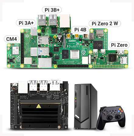
Application example
solar-powered control system for MCUs / development boards like:
Raspberry Pi / Jetson Nano / Arduino...

Note: for reference ONLY, the Raspberry Pi, display, solar panel are NOT included.
Resources introduction

- Solar panel input
recharging through DC-002 jack or screw terminal - TYPE-C recharging/output port
supports 5V power adapter for recharging
supports PD protocol quick charge adapter
supports PD/QC/FCP/PE/SFCP multi protocols output - USB output port
5V/3A regulated output
supports PD/QC/FCP/PE/SFCP multi protocols output
- Battery on/off switch
- BOOT button
- Quick charge indicator
- Solar panel status indicators
Solar Warning: lights up if solar panel is reversed
Solar Charge: lights up when recharging from solar panel
Solar Done: lights up when the battery is fully recharged - Battery life indicators
Outline Dimensions

What's in the box?
1 x solar manager
Need batteries? You will find our battery selection here
Resources

Note: the CM4 is NOT included. Please buy it separately if necessary.
The Nano Base Board (B) For Raspberry Pi Compute Module 4, is the Same Size As The CM4 and is suitable For Evaluating The Raspberry Pi CM4 Or Being Integrated Into End Products.
This module is Compact, Yet Complete, featuring: Standard CM4 Socket, 40PIN GPIO, Gigabit Ethernet, USB2.0, DSI, CSI, 3.5mm Audio Jack...
Specifications
CM4 SOCKET - suitable for all variants of Compute Module 4
NETWORKING - Gigabit Ethernet RJ45 connector
CONNECTOR - Raspberry Pi 40PIN GPIO header × 1
USB - USB 2.0 Type A connector × 1
DISPLAY - MIPI DSI port × 1 (15pin 1.0mm FPC connector)
CAMERA - MIPI CSI-2 port × 1 (15pin 1.0mm FPC connector)
VIDEO - Mini HDMI port × 1, supports 4K 30fps output
AUDIO - 3.5mm jack
STORAGE - Micro SD card socket for Compute Module 4 Lite (without eMMC) variants
POWER INPUT - 5V
DIMENSIONS - 56 × 41mm
What's On Board
- CM4 socket
suitable for all variants of Compute Module 4 - Micro SD card slot
for connecting a Micro SD card with pre-burnt image (Lite variant ONLY) - 40PIN GPIO header
for connecting sorts of HATs - Gigabit Ethernet RJ45 connector
- Power supply / Programming
5V power supply, or used for eMMC burning - 3.5mm audio jack
- User button
- USB2.0 connector
for connecting sorts of USB devices
- CSI connector
MIPI CSI camera interface - DSI connector
MIPI DSI display interface - MP1658
- Mini HDMI connector
supports 4K 30fps output - BOOT switch
ON: Switch USB to Type C interface, will enter download mode when powered on (configured as a large-capacity disk through RPI boot)
OFF: Switch USB to Type A interface, will not enter download mode when powered on (booted from eMMC or Micro SD card)
Outline Dimensions
What's in the box?
1 x CM4-NANO-B

1 x 2*20PIN color-coded straight pin header

Resources
WIKI: CM4-NANO-B

- It usually takes about 0.3s for partial refresh
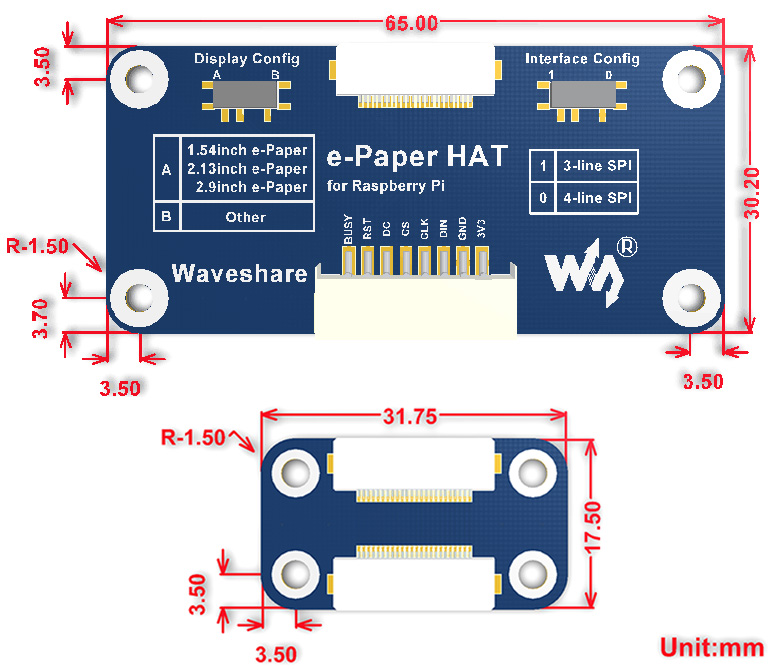
- Pi Header: standard Raspberry Pi 40PIN GPIO extension header, supports Raspberry Pi series boards
This is an E-Ink display HAT for Raspberry Pi, 7.5inch, 800×480 resolution, with embedded controller, communicating via SPI interface.
Due to the advantages like ultra low power consumption, wide viewing angle, clear display without electricity, it is an ideal choice for applications such as shelf label, industrial instrument, and so on.
Features- No backlight, keeps displaying last content for a long time even when power down
- Ultra low power consumption, basically power is only required for refreshing
- Standard Raspberry Pi 40PIN GPIO extension header, supports Raspberry Pi series boards, Jetson Nano
- SPI interface, for connecting with other controller boards like Raspberry/Arduino/Nucleo, etc.
- Onboard voltage translator, compatible with 3.3V/5V MCUs
- Comes with development resources and manual (examples for Raspberry Pi/Jetson Nano/Arduino/STM32)
Specifications
- Operating voltage: 3.3V~5V
- Interface: SPI
- Outline dimension: 170.2mm × 111.2mm
- Display size: 163.2mm × 97.92mm
- Dot pitch: 0.205 × 0.204
- Resolution: 800×480
- Display color: black, white
- Grey scale: 2
- Full refresh time: 5s
- Refresh power: 38mW(typ.)
- Standby power: <0.017mW
- Viewing angle: >170°
Revision History
Revision V2 has been released on 2019.11, the resolution is upgraded to 800×480, from 640×384 of V1. The hardware and interface of V2 are compatible with V1, however, the related software should be updated.
| SYMBOL | DESCRIPTION |
|---|---|
| VCC | 3.3V~5V |
| GND | Ground |
| DIN | SPI MOSI pin |
| CLK | SPI SCK pin |
| CS | SPI chip selection, low active |
| DC | Data/Command selection (high for data, low for command) |
| RST | External reset, low active |
| BUSY | Busy status output, low active |
Dimensions
What's in the box?
- 7.5inch e-Paper x1
- e-Paper Driver HAT x1
- RPi screws pack (2pcs) x1
- PH2.0 20cm 8Pin x1
 2
2 3
3 4
4
Resources
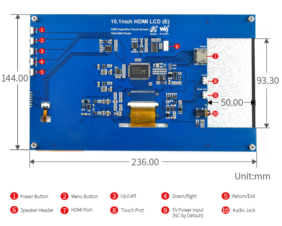
Size 10.1" | Resolution 1024×600 1024×600 | Display Port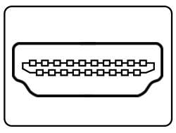 HDMI HDMI | Display Panel IPS IPS | Viewing Angle 170° 170° |
Touch Type Capacitive Capacitive | Touch Points 10-Points 10-Points | Touch Port USB USB | Touch Panel Toughened Glass Toughened Glass | Touch Panel Tech Fully Laminated Fully Laminated |
OSD Menu Brightness/Contrast Brightness/Contrast | Audio Output1 3.5mm Jack 3.5mm Jack | Audio Output2 4PIN Header 4PIN Header | Gaming Xbox360/PS4/Switch Xbox360/PS4/Switch |
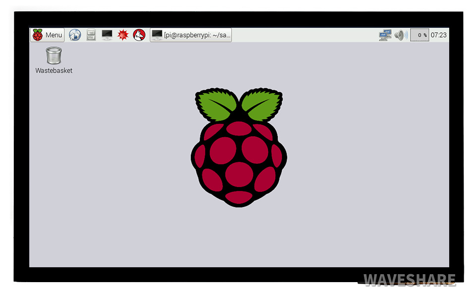
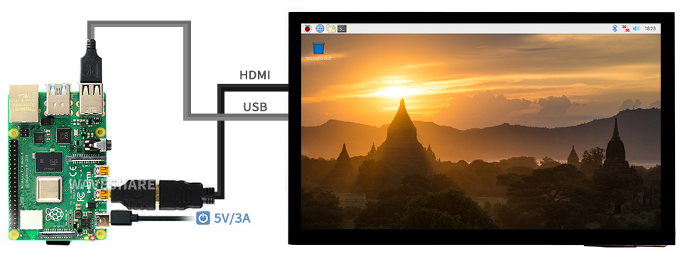
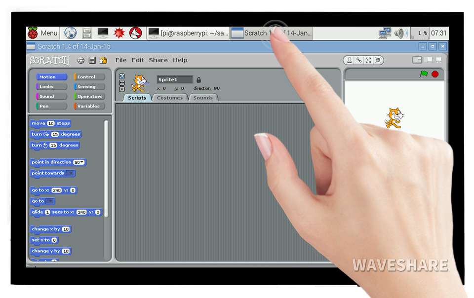
Supports Raspbian, 10-points touch, driver free
Supports Ubuntu / Kali / WIN10 IoT, single point touch, driver free
Supports Retropie, driver free
Supports all versions of Raspberry Pi
Working With Raspberry Pi 4
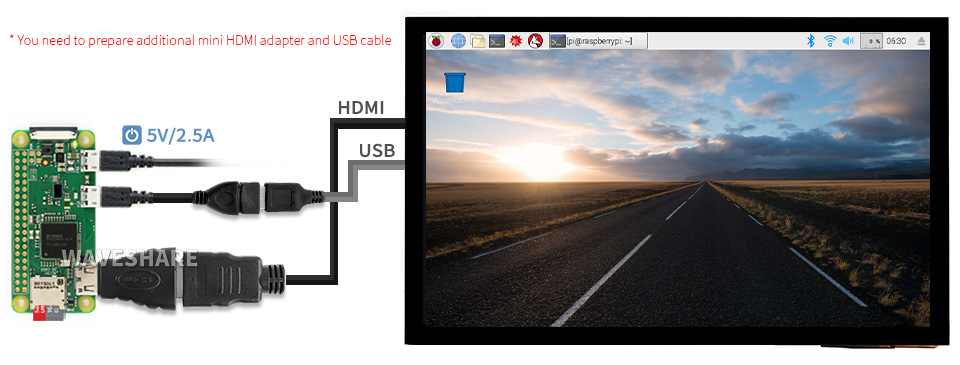
Working With Raspberry Pi Zero W
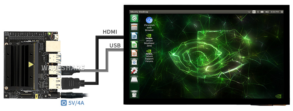
Working With AI Computer Jetson Nano
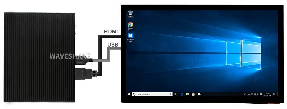
Working With Mini PC
IPS Panel
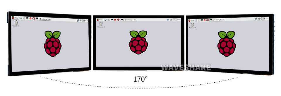

1) up to 10-points touch, depending on the operating system. 2) up to 6H hardness toughened glass panel. 3) fully laminated screen, better display experience, dust-proof.


* audio output from earphone jack and speaker header.
1 x HDMI cable
1 x HDMI to Micro HDMI Adapter
1 x USB-A to Micro-B cable
Resources

| PRODUCT TYPE | SC15 serial bus servo |
|---|---|
| TORQUE | [email protected]; 15kg.cm@6V; [email protected] |
| ROTATION ANGLE | 180° (servo mode angle control) / 360° (motor mode continuous rotation) |
| POS SENSOR RESOLUTION | 180° / 1024 |
| MECHANICAL LIMITED ANGLE | No Limit |
| OPERATING VOLTAGE | 4.8-8.4V |
| GEAR | high precision metal gear |
| IDLING SPEED | 0.18sec / 60°@4.8V 0.16sec / 60°@6V |
| ID RANGE | 0-253 |
| BAUDRATE | 38400bps ~ 1Mbps |
| FEEDBACK | Position, Load, Speed, Input Voltage |
| IDLING CURRENT | 200 mA |
| STALLING CURRENT | 1700 mA |
Application Examples
- Servos will provide various feedback like position, speed, torque lock, operating mode (servo mode, servo motor mode, etc.) for advanced projects requiring closed-loop automatic control
- Ideal choice for building quadruped robots, hexapod walkers, robotic arms and other robotic projects requiring multiple servos

* images here are for reference ONLY
Up To 253 Servos Can Be Connected In Series At The Same Time

Up To 17kg.Cm Torque On 8.4V Voltage, Suitable For Building Quadruped Robots, Hexapod Walkers, Robotic Arms And Other Robotic Projects Requiring Multiple Servos

Two-Way Feedback

The Servos Will Provide Various Feedback Like Position, Load, Speed, And Input Voltage,
In Real Time
precise rotation angle control, on servo mode

continuous rotation, on motor mode

Nylon and fiberglass case
Improved heat-resistance, size stability, rigidity, and mechanical performance

High strength aluminum servo wheels
Using T6061 aluminum alloy, good corrosion-resistance

High precision copper and steel gears
Ingenious combination of the two, lower operating noise, better stability and mechanical performance

- What's in the box?


Features at a glance
Using pogo pin connection, the Zero 2W can be easily attached
Easily compatible with the interfaces of Raspberry Pi 3B / 3B+ boards
Onboard headphone jack(extended from USB) and an additional speaker header
Onboard 4-ch USB ports, compatible with USB 2.0 / 1.1 transmission
Onboard RTL8152B Ethernet chip, support 1-ch RJ45 Ethernet port, 10 / 100 M adaptive
Not compatible with the first generation Zero
Based on Raspberry Pi Zero 2W
Use Pi Zero 2W to reproduce the original appearance of the 3B series as much as possible
More Cost-effective Choice

for reference only, Pi Zero 2W is NOT included
Using pogo pin connection, the Zero 2W can be easily attached
Onboard 4-ch USB Interface, 100M Ethernet Port and HDMI Port
Note: The Ethernet port does not support PoE function

Easy access to Pi 3B series HATs or other development projects
Note: the height of the GPIO is higher than the Pi 3B / 3B+
Support 3.5mm headphone jack and 4PIN speaker header
When headphone is plugged in, the speaker will be automatically disabled.
Outline dimensions
What's in the box?
1 x Zero 2W adapter board
4 x mounting screws
You will also need....
a Raspberry Pi Zero 2 W
Resources

Ideal for Temperature and Humidity meter, Humidifier, Digital Meter...

- No backlight, keeps displaying last content for a long time even when power down
- Ultra low power consumption, basically power is only required for refreshing
- I2C interface, for connecting with controller boards like Raspberry Pi/Arduino/STM32, etc.
- Onboard MOS voltage translating circuit, compatible with 3.3V/5V MCUs
- Comes with development resources and manual(driver board schematic, examples for Raspberry Pi/Arduino/STM32)
| operating voltage | 3.3V/5V | grey scale | 2 |
|---|---|---|---|
| interface | I2C | Partial Refresh Time | 0.3s |
| outline dimensions | 51 × 34 mm | full refresh time | 2s |
| display size | 41.35 × 28.11 mm | refresh power | <5mW (typ.) |
| Segments | 91 | standby current | <0.01uA (almost none) |
| display color | Black/White | viewing angle | >170° |

E-paper display utilizes microcapsule electrophoretic technology for displaying, the principle is: charged particles suspended in clear fluid will move to sides of microcapsule when electric field is applied, making the microcapsule become visible by reflecting ambient light, just as traditional printed paper.
E-paper display will clearly display images/texts under lamplight or natural light, requires no backlight, and features nearly up to 180° viewing angle. It is usually used as e-reader due to its paper-like effect.
For Use With Controller Boards Like Raspberry Pi/STM32/Arduino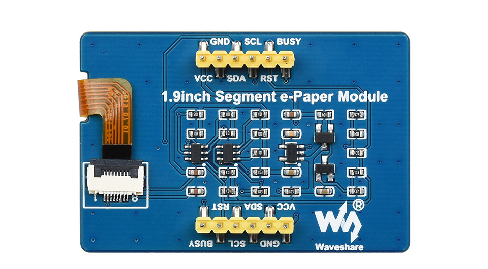
| VCC | Power (3.3V / 5V input) |
|---|---|
| GND | Ground |
| SDA | I2C data input |
| SCL | I2CI clock input |
| RST | External reset, low active |
| BUSY | Busy status output pin (high level means busy) |
Application Examples
Suitable For Temperature and Humidity meter, Humidifier, Digital Meter...
Outline dimensions
What's in the box?
1 x 1.9inch Segment e-Paper Module
1 x 6Pin Cable
Resources

Keeps your Pico running while recharging, monitoring battery via I2C, stackable design
SAFETY PRECAUTIONS
- Li-ion and Li-po batteries are quite unstable. They may cause fire, personal injury, or property damage, if they're not properly recharged or used.
- Do not reversely connect the polarities when recharging or discharging the battery. Do not use inferior charger/charging panel to recharge the battery.
- Do not mix use old batteries with new ones, avoid using batteries of different brands.
- When buying Lithium battery, should always make sure the battery specification is compatible with the expansion board. Choose batteries from formal manufacturer, and ensure the batteries will work stably and safely by aging test.
- Lithium batteries have limited cycle life, they will also deteriorate as time goes by. Should be replaced with new ones when the batteries reaching their max cycle life, or working over two years, whichever comes first.
- Should be placed carefully and properly, keep it away from inflammables and explosives articles, away from children, avoid any safety accident caused by careless storage.
The Pico-UPS-B is a dedicated UPS (Uninterruptible Power Supply) module designed for Raspberry Pi Pico. It incorporates Li-po battery switching charger with power path management, and voltage/current monitoring chip, allows monitoring the battery operating status via I2C bus. What's more, the male pin header make it possible to "stack" other modules on top.
- Standard Raspberry Pi Pico header, supports Raspberry Pi Pico series boards
- Incorporates Li-po battery switching charger with dynamic power path management, more stable power supply
- I2C bus communication, monitoring the battery voltage, current, power, and remaining capacity in real time
- Multi battery protection circuits: over charge/discharge protection, over current protection, short circuit protection, and reverse protection, more safe and stable
- Onboard recharging indicator, power indicator, easy to check the battery status
- Comes with development resources and manual (Raspberry Pi Pico C/C++ and MicroPython examples)
- Recharge voltage: 5V
- Control bus: I2C
- Battery support: 600mAh 3.7V Li-po battery
- Dimensions: 60 × 21mm
Raspberry Pi Pico header compatibility
onboard female pin header for direct attaching to Raspberry Pi Pico,
male pin header for stacking other modules
Raspberry Pi Pico and Pico-LCD-0.96 are NOT included.
What's On Board
- ETA6003
recharger chip - INA219
voltage/current monitoring chip - S8261
Li-po battery protection chip - FS8205
Li-po battery protection MOS - AO3400
reverse-proof MOS - SI2305
counter current preventing MOS
- Rapsberry Pi Pico header
for direct attaching to Raspberry Pi Pico - Power switch
- Activate button
activate the protection circuit after replacing battery - Battery header
for connecting 3.7V Li-po battery

Outline dimensions

What's in the box?
1 x UPS Module for Raspberry Pi Pico
Resources
Need batteries? You will find our battery selection here

Wide range audio sampling rate, headphone and speaker signal output at the same time.
The Pico-Audio is an audio expansion module designed for Raspberry Pi Pico, which incorporates CS4344 low power stereo decoder, and uses I2S bus for transmitting audio signal. It supports wide range audio sampling rate, allows headphone and speaker signal output at the same time.
- Standard Raspberry Pi Pico header, supports Raspberry Pi Pico series
- Standard 3.5mm audio jack, for connecting external headphone
- Dual channels speaker headers, for direct driving speakers
- 8~384000Hz audio sampling rate
- Stereo sound effect output
- Using 3-wire I2S, effectively reducing EMI
- Comes with development resources and manual (Raspberry Pi Pico audio play code, sound card code)
| Operating voltage | 5V | Logic level | 3.3V |
|---|---|---|---|
| Audio decoder | CS4344 | Audio bus | I2S |
| DAC SNR | 106 dB | Speaker driving | 2.6W/channel (4Ω BTL) |
Raspberry Pi Pico header compatibility
onboard female pin header for direct attaching to Raspberry Pi Pico,
male pin header for stacking other modules
Raspberry Pi Pico is NOT included.
What's On Board
- Dual channels 4-wire speaker header
- SMD adjustable resistor
speaker output volume adjustment - Audio decoder output observing points
- 3.5mm standard headphone jack
- RT9193-33
3.3V linear regulator
- CS4344
audio decoder, 3-wire I2S bus - APA2068
audio power amplifier - Raspberry Pi Pico header
for connecting Raspberry Pi Pico, stackable design

Example usage

Speakers, Pico and USB cable are not included
Outline dimensions

What's in the box?
1 x Pico-Audio module
Resources

Allows multiple input devices to share one HDMI screen, high-resolution and smooth
| Input Interface | HDMI x 3 |
|---|---|
| Support 4K/2K@30Hz and 4K/2K (YCbCr420) @60Hz resolution | |
| Built-in input Equalizer, can automatically adjust the input signal | |
| Output Interface | HDMI x 1 |
| Built-in output drive regulator, can automatically adjust the output signal amplitude | |
| Interface Standard | Support HDMI 1.4b and DVI1.0 standard |
| Transfer Speed | Up to 3Gbps |
Allows Multiple Input Devices To Share One HDMI Screen,
such as Raspberry Pi, PC, Smartphone...
Support 4K/2K@30Hz and 4K/2K (YCbCr420)@60Hz resolution
Clearer & Smoother image, No Delay In Sound
Built-in Adjustment Function for Input and Output, Free to Transmit With Different Cables
Data Transfer Speed Up To 3Gbps
No additional Power Supply required, Plug And Play With HDMI Cable
Almost as small as a credit card, easy to carry, space-efficient

What's in the box?
1 x HDMI switch


Low power, wide viewing angle, paper-like effect without electricity
Ideal for price tags, shelf labels, industrial instruments...
- Advanced Color ePaper (ACeP) technology, supports 7-Color display
- No backlight, keeps displaying last content for a long time even when power down
- Ultra low power consumption, basically power is only required for refreshing
- Standard Raspberry Pi 40PIN GPIO extension header, supports Raspberry Pi series boards, Jetson Nano
- SPI interface, for connecting with controller boards like Raspberry Pi/Jetson Nano/Arduino/STM32, etc.
- Onboard voltage translator, compatible with 3.3V/5V MCUs
- Comes with development resources and manual(driver board schematic, examples for Raspberry Pi/Arduino/STM32)
Specifications
| operating voltage | 3.3V/5V | display color | 7-Color |
|---|---|---|---|
| interface | 3-wire SPI, 4-wire SPI | grey scale | 2 |
| outline dimensions | 170.2 × 111.2mm | full refresh time | 35s |
| display size | 160 × 96mm | refresh power | <49.4mW (typ.) |
| DOT PITCH | 0.2 × 0.2 mm | standby current | <0.01uA (almost none) |
| RESOLUTION | 800×480 pixels | viewing angle | >170° |
Advantages of EINK
E-paper display utilizes microcapsule electrophoretic technology for displaying, the principle is: charged particles suspended in clear fluid will move to sides of microcapsule when electric field is applied, making the microcapsule become visible by reflecting ambient light, just as traditional printed paper.
E-paper display will clearly display images/texts under lamplight or natural light, requires no backlight, and features nearly up to 180° viewing angle. It is usually used as e-reader due to its paper-like effect.
Compatible With Raspberry Pi Series Boards, Jetson Nano
For Use With Controller Boards Like Raspberry Pi/Jetson Nano/Arduino/STM32
| VCC | Power (3.3V / 5V input) |
|---|---|
| GND | Ground |
| DIN | SPI MOSI pin |
| SCLK | SPI SCK pin |
| CS | SPI chip selection, low active |
| DC | Data/Command selection (high for data, low for command) |
| RST | External reset, low active |
| BUSY | Busy status output pin |
Application examples
Suitable for price Tags, asset/equipment Tags, shelf labels, conference name tags...
Outline dimensions

What's in the box?
1 x 7.3inch e-Paper (F)
1 x Driver Board and FFC cable
1 x PH2.0 20cm 8Pin
1 x RPi screws pack (2pcs)
Resources

Specifications
- RP2040 microcontroller chip designed by Raspberry Pi in the United Kingdom
- Dual-core Arm Cortex M0+ processor, flexible clock running up to 133 MHz
- 264KB of SRAM, and 2MB of onboard Flash memory
- Onboard FPC 8PIN connector, adapting USB Type-C port via adapter board
- Castellated module allows soldering direct to carrier boards
- USB 1.1 with device and host support
- Low-power sleep and dormant modes
- Drag-and-drop programming using mass storage over USB
- 20 × multi-function GPIO pins
- 2 × SPI, 2 × I2C, 2 × UART, 4 × 12-bit ADC, 16 × controllable PWM channels
- Accurate clock and timer on-chip
- Temperature sensor
- Accelerated floating-point libraries on-chip
- 8 × Programmable I/O (PIO) state machines for custom peripheral support


Comprehensive SDK, Dev Resources, Tutorials To Help You Easily Get Started
20 × Multi-Function GPIO Pins

What's in the box?
1 x RP2040-Tiny
1 x RP2040-Tiny-Adapter
1 x 8PIN FPC cable ~15cm
Resources
Wiki: www.waveshare.com/wiki/RP2040-Tiny

Supports Ubuntu / Kali / WIN10 IoT, single point touch, driver free
Supports Retropie, driver free
Supports all versions of Raspberry Pi
Working With Raspberry Pi 4

Audio Feature


What's in the box?
1 x 15.6inch HDMI LCD (H) (with case)
1 x Power adapter EU plug 12V
1 x HDMI cable
1 x HDMI to Micro HDMI Adapter
1 x USB type A plug to micro B plug cable
Resources
Wiki: www.waveshare.com/wiki/15.6inch_HDMI_LCD_(H)_(with_case)

The Raspberry Pi E-Ink Display HAT, featuring a 2.13-inch screen with a crisp 250x122 resolution. Equipped with an embedded controller and communicating via the SPI interface, this display supports partial refresh.
Thanks to its remarkable benefits, including exceptionally low power consumption, a broad viewing angle, and the ability to display content without constant electricity, it emerges as the perfect solution for various applications. Its versatility makes it an excellent fit for uses such as shelf labeling, industrial instrumentation, and more.Features
- No backlight, keeps displaying last content for a long time even when power down
- Ultra low power consumption, basically power is only required for refreshing
- Standard Raspberry Pi 40PIN GPIO extension header, supports Raspberry Pi series boards, Jetson Nano
- SPI interface, for connecting with other controller boards like Arduino/Nucleo, etc.
- Onboard voltage translator, compatible with 3.3V/5V MCUs
- Comes with development resources and manual (examples for Raspberry Pi/Jetson Nano/Arduino/STM32)
What's in the box?
1 x 2.13inch E-Ink display HAT for Raspberry Pi 250x122
Resources
- Wiki : www.waveshare.com/wiki/2.13inch_e-Paper_HAT


Specifications
- NETWORK SUPPORT 4G/3G/2G/LPWA
- GAIN 5dBi
- FREQUENCY RANGE 315~500MHz
- 690~2700MHz
- CONNECTOR SMA male connector
- POWER INPUT 10W MAX
- OUTPUT IMPEDANCE 50Ω
- SWR ≤2.0
- POLARIZATION Vertical
- ANTENNA HEIGHT 433/470M version: ~15cm, 868/915M version: ~11cm
- CABLE LENGTH 3m
- COLOUR Black
- WATERPROOF IP65
What's in the box?
1 x Outdoor Waterproof LPWA Antenna: 5dBi High Gain, Magnetic Base, Multi-Frequency Support
Outline Dimensions:


Suitable For LPWA, SMA Male Connector, 2dBi
Outline Dimensions
Specifications
- NETWORK SUPPORT LPWA
- GAIN 2dBi
- FREQUENCY RANGE 423~433MHz, 833~903MHz
- CONNECTOR SMA male connector
- OUTPUT IMPEDANCE 50Ω
- ANTENNA LENGTH 11cm
- SWR ≤2.0
- MATERIAL ABS
- POLARIZATION Vertical
- COLOUR Black
What's in the box?
1 x 2dBi LPWA LoRa Antenna

This product is a LoRa Gateway module that incorporates a new-generation SX1302/3 normal band chip. It has lots of advantages including long-range transmission, large capacity node, and high receiving sensitivity. In addition, SX1303 supports concurrent communication. Due to the outstanding performance of SX1302/3 on low power consumption, the heat dissipation design of the Gateway can be simplified, thus reducing material cost, also achieving a smaller size.
LoRaWAN Gateway Module features
- Integrates Semtech SX1302/3 normal band and SX1250 radio RF frond-end chip
- Onboard PA and LNA, features +26dBm emit power and -141dBm high sensitivity receiving gain
- The SX1303 supports Fine Timestamp and network positioning based on time difference of arrival (TDOA)
- 52-pin Mini-PCIe socket for easy integration into various embedded systems
- Onboard 4 LED indicators for module operating status
- Comes with development resources and manual (example in C)
HAT features
- Standard Raspberry Pi 40PIN GPIO extension header, supports Raspberry Pi series boards
- Incorporate L76K module with GPS/BD support, provide accurate clock and location info for gateway module
- Comes with development resources and manual (example in C)
| BAND CHIP | SX1302 | SX1303 | ||
|---|---|---|---|---|
| 868M | 915M | 868M | 915M | |
| FREQUENCY RANGE | 868M: EU868, IN865, RU864 915M: US915, AU915, KR920 | |||
| POWER SUPPLY | 5V | |||
| MODULATION | LoRa/(G)FSK | |||
| EMIT POWER | +26dBm@5V | |||
| RECEIVING SENSITIVITY | -141dBm@125KHz/SF12 -121dBm@125KHz/SF5 | |||
| OVERALL POWER CONSUMPTION | emitting: 454mA@5V receiving: 42mA@5V sleep: 11mA@5V | emitting: 427mA@5V receiving: 40mA@5V sleep: 8mA@5V | ||
| COMMUNICATION BUS | SPI, I2C | |||
| EXTERNAL CONNECTOR | Mini-PCIe | |||
| OPERATING TEMPERATURE | -40~85℃ | |||
| DIMENSIONS | 50.95 x 30mm | |||
The New Generation LoRa Spread Spectrum Technology,
Higher Anti-Interference Performance, Longer Communication Distance
Network Positioning Based On Time Difference Of Arrival (TDOA)
What's On Board
- SX1302/3 LoRaWAN Gateway module
- Mini-PCIe socket and buckle
- L76K module
- RT9193-33 power chip
- Status indicator
PWR: power indicator
RXD/TXD: UART RX/TX indicator
PPS: GPS status indicator - Raspberry Pi GPIO header
for connecting with Raspberry Pi series boards - L76K antenna connector
- LoRa Gateway antenna connector
- Battery holder
supports ML1220 rechargeable cell, for preserving ephemeris information and hot starts
Module Pinout Definition

HAT Pinout Definition

Outline Dimensions

What's in the box?
1 x SX1303 868M LoRaWAN Gateway HAT
Resources
Wiki: www.waveshare.com/wiki/SX1302_LoRaWAN_Gateway_HAT

- Adopts IPS panel, 1024×600 resolution*, with 170° viewing angle
- Adopts DVI interface for higher communication speed
- Based on the Raspberry Pi Pico with onboard 40PIN header
- Built in OSD menu for brightness/contrast adjustment
- Available in 7inch and 10.1inch display sizes
- Suitable for advertisement picture display and other application scenarios
- Comes with online development resources and manual (examples for Raspberry Pi Pico C/C++)
- OPERATING VOLTAGE5VRESOLUTION: 1024×600 pixels
- COMMUNICATION INTERFACED: VI
- DISPLAY PANEL: IPS
- DISPLAY SIZE: 7inch: 154.21×85.92mm
- PIXEL SIZE: 7inch: 0.1506×0.1432mm


PIN Definition

Interface Introduction

Outline Dimensions


What's in the box?
1 x 7 inch DVI Display Module for Raspberry Pi Pico 1024×600 Pixel(Raspberry Pi Pico Not Included)
Resources
Wiki: www.waveshare.com/wiki/PICO-DVI-LCD


Using SPI Communication, Supports 65K Color Display, Can Be Used To Display Key
Information, Status Indicator Messages Or Small Graphics
- Standard Raspberry Pi 40PIN GPIO header, compatible with Raspberry Pi series boards
- 1.3inch IPS LCD Main Screen with built in ST7789 driver chip, SPI interface communication, wide viewing angle, supports 65K color display, 240×240 resolution
- Dual 0.96inch LCD secondary screens with built in ST7735S driver chip, SPI interface communication, supports 65K color display, 160×80 resolution, can be used to display key informations, status indicator messages or small graphics
- Onboard 2x user-defined keys for extended applications
- Comes with online development resources and manual (Raspberry Pi/VisionFive2/Arduino/STM32, etc.)
Supports Customizing The Key Function, Easy To Use

Outline Dimensions
What's in the box?
1 x Zero LCD HAT (A)
1 x Standoffs pack
Resources
http://www.waveshare.com/wiki/OLED/Zero_LCD_HAT_(A)