
WaveShare


The Raspberry Pi E-Ink Display HAT, featuring a 2.13-inch screen with a crisp 250x122 resolution. Equipped with an embedded controller and communicating via the SPI interface, this display supports partial refresh.
Thanks to its remarkable benefits, including exceptionally low power consumption, a broad viewing angle, and the ability to display content without constant electricity, it emerges as the perfect solution for various applications. Its versatility makes it an excellent fit for uses such as shelf labeling, industrial instrumentation, and more.Features
- No backlight, keeps displaying last content for a long time even when power down
- Ultra low power consumption, basically power is only required for refreshing
- Standard Raspberry Pi 40PIN GPIO extension header, supports Raspberry Pi series boards, Jetson Nano
- SPI interface, for connecting with other controller boards like Arduino/Nucleo, etc.
- Onboard voltage translator, compatible with 3.3V/5V MCUs
- Comes with development resources and manual (examples for Raspberry Pi/Jetson Nano/Arduino/STM32)
What's in the box?
1 x 2.13inch E-Ink display HAT for Raspberry Pi 250x122
Resources
- Wiki : www.waveshare.com/wiki/2.13inch_e-Paper_HAT


Specifications
- NETWORK SUPPORT 4G/3G/2G/LPWA
- GAIN 5dBi
- FREQUENCY RANGE 315~500MHz
- 690~2700MHz
- CONNECTOR SMA male connector
- POWER INPUT 10W MAX
- OUTPUT IMPEDANCE 50Ω
- SWR ≤2.0
- POLARIZATION Vertical
- ANTENNA HEIGHT 433/470M version: ~15cm, 868/915M version: ~11cm
- CABLE LENGTH 3m
- COLOUR Black
- WATERPROOF IP65
What's in the box?
1 x Outdoor Waterproof LPWA Antenna: 5dBi High Gain, Magnetic Base, Multi-Frequency Support
Outline Dimensions:


This product is a LoRa Gateway module that incorporates a new-generation SX1302/3 normal band chip. It has lots of advantages including long-range transmission, large capacity node, and high receiving sensitivity. In addition, SX1303 supports concurrent communication. Due to the outstanding performance of SX1302/3 on low power consumption, the heat dissipation design of the Gateway can be simplified, thus reducing material cost, also achieving a smaller size.
LoRaWAN Gateway Module features
- Integrates Semtech SX1302/3 normal band and SX1250 radio RF frond-end chip
- Onboard PA and LNA, features +26dBm emit power and -141dBm high sensitivity receiving gain
- The SX1303 supports Fine Timestamp and network positioning based on time difference of arrival (TDOA)
- 52-pin Mini-PCIe socket for easy integration into various embedded systems
- Onboard 4 LED indicators for module operating status
- Comes with development resources and manual (example in C)
HAT features
- Standard Raspberry Pi 40PIN GPIO extension header, supports Raspberry Pi series boards
- Incorporate L76K module with GPS/BD support, provide accurate clock and location info for gateway module
- Comes with development resources and manual (example in C)
| BAND CHIP | SX1302 | SX1303 | ||
|---|---|---|---|---|
| 868M | 915M | 868M | 915M | |
| FREQUENCY RANGE | 868M: EU868, IN865, RU864 915M: US915, AU915, KR920 | |||
| POWER SUPPLY | 5V | |||
| MODULATION | LoRa/(G)FSK | |||
| EMIT POWER | +26dBm@5V | |||
| RECEIVING SENSITIVITY | -141dBm@125KHz/SF12 -121dBm@125KHz/SF5 | |||
| OVERALL POWER CONSUMPTION | emitting: 454mA@5V receiving: 42mA@5V sleep: 11mA@5V | emitting: 427mA@5V receiving: 40mA@5V sleep: 8mA@5V | ||
| COMMUNICATION BUS | SPI, I2C | |||
| EXTERNAL CONNECTOR | Mini-PCIe | |||
| OPERATING TEMPERATURE | -40~85℃ | |||
| DIMENSIONS | 50.95 x 30mm | |||
The New Generation LoRa Spread Spectrum Technology,
Higher Anti-Interference Performance, Longer Communication Distance
Network Positioning Based On Time Difference Of Arrival (TDOA)
What's On Board
- SX1302/3 LoRaWAN Gateway module
- Mini-PCIe socket and buckle
- L76K module
- RT9193-33 power chip
- Status indicator
PWR: power indicator
RXD/TXD: UART RX/TX indicator
PPS: GPS status indicator - Raspberry Pi GPIO header
for connecting with Raspberry Pi series boards - L76K antenna connector
- LoRa Gateway antenna connector
- Battery holder
supports ML1220 rechargeable cell, for preserving ephemeris information and hot starts
Module Pinout Definition

HAT Pinout Definition

Outline Dimensions

What's in the box?
1 x SX1303 868M LoRaWAN Gateway HAT
Resources
Wiki: www.waveshare.com/wiki/SX1302_LoRaWAN_Gateway_HAT

- Adopts IPS panel, 1024×600 resolution*, with 170° viewing angle
- Adopts DVI interface for higher communication speed
- Based on the Raspberry Pi Pico with onboard 40PIN header
- Built in OSD menu for brightness/contrast adjustment
- Available in 7inch and 10.1inch display sizes
- Suitable for advertisement picture display and other application scenarios
- Comes with online development resources and manual (examples for Raspberry Pi Pico C/C++)
- OPERATING VOLTAGE5VRESOLUTION: 1024×600 pixels
- COMMUNICATION INTERFACED: VI
- DISPLAY PANEL: IPS
- DISPLAY SIZE: 7inch: 154.21×85.92mm
- PIXEL SIZE: 7inch: 0.1506×0.1432mm


PIN Definition

Interface Introduction

Outline Dimensions


What's in the box?
1 x 7 inch DVI Display Module for Raspberry Pi Pico 1024×600 Pixel(Raspberry Pi Pico Not Included)
Resources
Wiki: www.waveshare.com/wiki/PICO-DVI-LCD


Using SPI Communication, Supports 65K Color Display, Can Be Used To Display Key
Information, Status Indicator Messages Or Small Graphics
- Standard Raspberry Pi 40PIN GPIO header, compatible with Raspberry Pi series boards
- 1.3inch IPS LCD Main Screen with built in ST7789 driver chip, SPI interface communication, wide viewing angle, supports 65K color display, 240×240 resolution
- Dual 0.96inch LCD secondary screens with built in ST7735S driver chip, SPI interface communication, supports 65K color display, 160×80 resolution, can be used to display key informations, status indicator messages or small graphics
- Onboard 2x user-defined keys for extended applications
- Comes with online development resources and manual (Raspberry Pi/VisionFive2/Arduino/STM32, etc.)
Supports Customizing The Key Function, Easy To Use

Outline Dimensions
What's in the box?
1 x Zero LCD HAT (A)
1 x Standoffs pack
Resources
http://www.waveshare.com/wiki/OLED/Zero_LCD_HAT_(A)

Supports Charging And Power Output At The Same Time, With Dynamic Path Management, Stable 5V Output
Comes with online development resources and manual
The UPS HAT (D) is an uninterruptible power supply (UPS) expansion board specially designed for the Raspberry Pi series. Onboard switching Li battery charging chip with path management, boost converter chip, and voltage/current monitoring chip which can monitor the operating state of the batteries via the I2C interface.
- Adopts pogo pins connector design, compatible with Raspberry Pi 3 / 3B+ / 4B, etc.
- Onboard Li battery charging chip, with dynamic path management, more stable power supply
- Onboard boost converter chip for stable 5V power output
- I2C bus communication, monitoring the batteries voltage, current, power, and remaining capacity in real time
- Multi battery protection circuits: over charge/discharge protection, over current protection, short circuit protection, more safe and stable
- Onboard MCU management, supports detecting power connection and booting the Raspberry Pi
- Supports displaying battery level on the system, easy to check the battery remaining capacity
- Onboard LED indicators for monitoring the battery operating status
- Comes with online development resources and manual
| OUTPUT VOLTAGE | 5V |
|---|---|
| CONTROL BUS | I2C |
| BATTERY SUPPORT | 21700 Li battery × 2 (in parallel, NOT included) |
| CHARGER SUPPORT | 5V (Type-C port) |
| DIMENSIONS | 56 × 85mm |
| MOUNTING HOLE SIZE | 3.0mm |
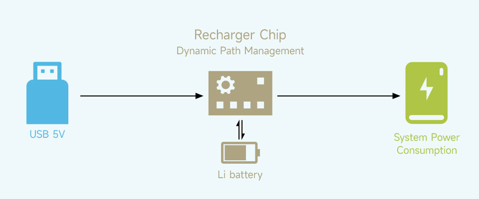
- When connected to the external power supply, the system will be powered and the battery will be charged at the same time, and the battery will be disconnected after being fully charged to avoid battery life damaging caused by frequent charging and discharging
- When the external power supply is insufficient, the battery will provide power output together with the external power supply at the same time to ensure system normal operation
- When the external power supply is connected, the system will keep running normally even when the battery fails or is taken out. And automatically switch over to batteries output if the external power supply is unavailable, keeps the system running without any trouble
Longer Battery Life
Onboard Warning Indicators, Easy To Check If The Battery Is Connected Correctly
Powering The Raspberry Pi Via Pogo Pins, Without Using Any GPIO Resource,
Compatible With Raspberry Pi 3 / 3B+ / 4B, Etc.
Monitoring The Batteries Voltage, Current, Power, And Remaining Capacity Via I2C
When the voltage dips too low, it is possible to save files properly and then shut down the system by software, to avoid any data loss
Detecting Power Connection
Easy To Check The Battery Status In Real-Time, And Automatically Shutdown When The Battery Level Is Low. Onboard MCU Chip For Detecting Power Connection And Automatically Rebooting The Raspberry Pi
Outline Dimensions
What's in the box?
1 x UPS HAT (D)
1 x Acrylic protection panel
1 x Screws pack
You might need to grab some 21700 batteries
Resources
Wiki: http://www.waveshare.com/wiki/UPS_HAT_(D)

Note: We have tested this unit successfully on Zero and Zero 2.
The ETH/USB HUB HAT (B) is an Ethernet and USB HUB designed for Raspberry Pi, providing 1x RJ45 Ethernet port and 3x USB 2.0 ports. It's pogo pin design is specialized for Zero series, while the onboard normal USB connector can be used to connect with other Raspberry Pi boards through a USB cable.
Specifications
- 3x extended USB ports, compatible with USB 2.0 / 1.1
- Incorporates RTL8152B Ethernet chip, supports 1x RJ45 Ethernet port, 10/100M auto-negotiation
- Pogo pin design, for direct connecting with Raspberry Pi Zero/Zero W/Zero WH
- USB HUB connector, for connecting with Raspberry Pi 4B/3B /3A /2B through USB cable

Two different lids included


What's in the box ?
1 x ETH/USB HUB HAT (B)
1 x ABS case
1 x Rubber feet 4PCS
1 x Screws pack
Screwdriver x1
Resources
Wiki: ETH/USB_HUB_HAT_(B)

GNSS Positioning, As Well As Bluetooth Data Transfer
- Standard Raspberry Pi Pico header, supports Raspberry Pi Pico series boards
- UART communication, serial AT commands control
- Supports SMS, phone call, GPRS, DTMF, HTTP, FTP, MMS, email, etc.
- Bluetooth3.0 support, allows Bluetooth data transfer
- RTC real time clock, with rechargeable Li-po battery
- Integrates 3.7V Li-po battery connector and recharge circuit, allows being powered from external rechargeable Li-po battery, or recharging it in turn
- Onboard microphone, together with speaker header, can be used to make phone call
- 2x LED indicators, for monitoring the module operating status
- Onboard nano SIM card slot, supports 2G/4G SIM card *
- Comes with development resources and manual (Raspberry Pi Pico C/C++ and MicroPython examples)
| SIM868 | |||
|---|---|---|---|
| Applicable region | most countries/regions | ||
| FREQUENCY BAND | |||
| NB-IoT | N/A | B1/B2/B3/B4/B5/B8/B12/B13/B18/B19/ B20/B25/B26/B28/B66/B71/B85 | LTE-FDD: B1/B3/B5/B8/B20/B28 |
| Cat-M | N/A | B1/B2/B3/B4/B5/B8/B12/B13/B14/B18/ B19/B20/B25/B26/B27/B28/B66/B85 | N/A |
| 2G | GSM 850/EGSM 900/DCS 1800/PCS 1900 MHz | N/A | N/A |
| GNSS | GPS, GLONASS, BeiDou | GPS, GLONASS, BeiDou, Galileo | N/A |
| DATA RATE | |||
| NB-IoT(Kbps) | - | 136(DL)/150(UL) | 26.15(DL)/62.5(UL) |
| Cat-M(Kbps) | - | 589(DL)/1119(UL) | - |
| 2G(Kbps) | 85.6(DL)/85.6(UL) | - | - |
| OTHERS | |||
| Communication protocol | TCP/UDP/HTTP/SSL/FTP /POP3/SMTP/MQTT... | TCP/UDP/HTTP/HTTPS/TLS/DTLS /PING/LWM2M/COAP/MQTT... | |
| Power supply | External Li-po battery OR Raspberry Pi Pico USB port | ||
| Battery interface | 3.7V ~ 4.2V | ||
| Logic level | 3.3V | ||
| Module standalone current | Idle mode: 12mA | Idle mode: 10mA | Idle mode: 5.6mA |
| Sleep mode: 0.65mA | Sleep mode: 1.2mA | Sleep mode: 0.4mA | |
| Backup mode: 8uA | PSM mode: 3.2uA | PSM mode: 3.4uA | |
| Audio input/output | onboard microphone, with speaker header | N/A | |
| Indicator | NET: network indicator Charge: recharge indicator | ||
| Switch | Li-po battery and USB power supply switch | Li-po battery power supply switch | |
| SIM card | 2G SIM card (1.8V / 3V) | NB-IoT / Cat-M card (1.8V ONLY) | NB card (1.8V / 3V) |
| Antenna connector | LTE, GNSS, BT | LTE, GNSS | LTE |
| Dimensions | 76.15 × 24.00mm | 73.5 × 24.00mm | |
The Pico Can Be SMD-Mounted (Left), Or Attached Via Female Header (Right)
Connecting With Other Expansion Module And Antenna
Supports Communication Protocols Including: TCP/UDP/HTTP/SSL/FTP/POP3/SMTP/MQTT

GNSS Support Including GPS, GLONASS, BeiDou

Onboard Microphone, Together With Speaker Header, For Making Phone Call
Supports Sending SMS, MMS, And Email Via AT Commands
Allows Bluetooth Wireless Communication With Bluetooth3.0 Devices
Pinout Definition
Outline Dimensions
What's in the box?
1 x Pico-SIM868-GSM/GPRS/GNSS
1 x LTE antenna
1 x GPS antenna
1 x Bluetooth antenna
2 x 20PIN female pin header
1 x 40PIN male pin header
1 x 3.7V rechargeable Li-po battery
1 x Speaker
Resources
Wiki: Pico-SIM868-GSM/GPRS/GNSS

Raspberry Pi 5 provides two four-lane MIPI connectors, each of which can support either a camera or a display. These connectors use the same 22-way, 0.5mm-pitch “mini” FPC format and require adapter cables to connect to the 15-way, 1mm-pitch “standard” format connectors on current Raspberry Pi camera and display products.
Note that a camera cable should not be used with a display, and vice versa.
Black EMI Shielding Film On Both Sides, Enhancing Anti-Interference Performance More Stable Signal Transmission

What's in the box?
1 x Raspberry Pi 5 Display Adapter Cable

Raspberry Pi 5 provides two four-lane MIPI connectors, each of which can support either a camera or a display. These connectors use the same 22-way, 0.5mm-pitch “mini” FPC format and require adapter cables to connect to the 15-way, 1mm-pitch “standard” format connectors on current Raspberry Pi camera and display products.
Note that a camera cable should not be used with a display, and vice versa.
What's in the box?
1 x Raspberry Pi 5 Display Adapter Cable

| INPUT VOLTAGE | 5V DC (supplied via four-pin fan header on Raspberry Pi 5) |
|---|---|
| FAN SPEED CONTROL | Pulse width modulation control with tachometer |
| MAXIMUM AIRFLOW | 2.35 CFM |
| FAN SPEED | 8000±10%RPM |
| MATERIAL | Anodised aluminium |
Matching The Size And Mounting Holes Of The Raspberry Pi 5, Combines An Aluminium Heatsink With An Active Cooling Fan To Accelerate Heat Dissipation
Connect The 4pin Cable To The Fan Header On Raspberry Pi 5, And Fix The Active Cooler Via M2.5 Nylon Screws

Raspberry Pi 5 Cooling Solution Comparing
Outline Dimensions
What's in the box?
1 x Active Cooler for Raspberry Pi 5 Aluminium Heatsink with Thermal Pads (Raspberry Pi 5 not included)
Raspberry Pi 5 provides two four-lane MIPI connectors, each of which can support either a camera or a display. These connectors use the same 22-way, 0.5mm-pitch “mini” FPC format and require adapter cables to connect to the 15-way, 1mm-pitch “standard” format connectors on current Raspberry Pi camera and display products.
Note that a camera cable should not be used with a display, and vice versa.
What's in the box?
1 x Raspberry Pi 5 Display Adapter Cable

Mini, Practical And Neat
Suitable For Evaluating The Raspberry Pi CM4 Or Being Integrated Into End

Dual Gigabit Ethernet Base Board
- CM4 SOCKET: suitable for all variants of Compute Module 4
- NETWORKING" Dual Gigabit Ethernet RJ45 connectorUSBUSB 2.0 Port
- PIN HEADER: Raspberry Pi 40PIN GPIO header
- STORAGE: TF card socket for Compute Module 4 Lite (without eMMC) variants
- FAN HEADER: 4-wire SH1.0 port, allows speed adjustment and measurement, 5V
- POWER INPUT: 5V, Type-C interfaceDIMENSIONS55.0 × 68.0mm
Standard CM4 Socket And 40PIN GPIO Header
Suitable For Compute Module 4 Lite/EMMC Series Module
Rich Interfaces
What's On Board
- 40PIN GPIO header
for connecting sorts of HAT - CM4 Socket
suitable for all variants of Compute Module 4 - RJ45 Dual Gigabit Ethernet Port
Dual RJ45 Gigabit Ethernet ports, 10/100/1000M compatible
ETHERNET 0: CM4 original network port
ETHERNET 1: PCIe extended network port - USB 2.0 Type A port
for connecting sorts of USB devices - FAN header
for connecting cooling fan, allows speed adjustment and measurement - Reset button
- Boot switch
ON: CM4 would be booted from USB-C interface
OFF: CM4 would be booted from eMMC or TF car
- Type-C port
5V/2.5A power supply, or used for eMMC programming - TF card slot
for connecting a TF card with pre-burnt image (Lite variant ONLY) - RTL8111H
Gigabit NIC chip - Indicator
PWR: indicating the power supply status of Raspberry Pi
SYS: indicating the working status of Raspberry Pi - SYSTEM switch
EEPROM_WP: Prevent EEPROM from being overwritten
WiFi_DIS: WiFi disabled, only for CM4 version with wireless
BT_DIS: Bluetooth disabled, only for CM4 version with wireless

What's in the box?
1 x Mini Dual Gigabit Ethernet Base Board Designed for Raspberry Pi Compute Module 4
Resources
WIKI: www.waveshare.com/wiki/CM4-DUAL-ETH-MINI

LoRaWAN Protocol Support

Features At A Glance
The Pico-LoRa-SX1262-XXXM is LoRa node expansion module designed for Raspberry Pi Pico based on SX1262 with better performance than the SX127X series. The LoRa modulation technology solves the balancing problem between transmission distance, interference immunity, and power consumption that traditional solutions aren't able to deal with.
It supports LoRaWAN protocol, which allows it to connect the TTN, ChirpStack servers through a LoRa gateway to use LoRa Cloud service fast and easily.
- Standard Raspberry Pi Pico header, supports Raspberry Pi Pico series boards
- Supports LoRaWAN protocol, different frequency bands are available
- Adopts active temperature compensation crystal oscillator, ensuring stable long-term operating in extreme high/low temperature conditions
- Supports FSK, GFSK, LoRa modulations, outstanding anti-blocking performance and ultra long communication distance
- PH1.25 battery header and recharge controller, allows connecting rechargeable Lithium battery
- High receiving sensitivity (up to -148dBm), programmable emitting power (up to 22dBm)
- Supports preamble detection, with CRC, up to 256 bytes data packet engine
- Comes with development resources and manual (example in C)
Specifications
| FREQUENCY BAND | 868M (863~870MHZ) | ||
|---|---|---|---|
| RFID | SX1262 | ||
| Emiting power | 22dBm | ||
| Emiting current | 107mA@22dBm | 118mA@22dBm | |
| Receiving current | 5.3mA@125KHz | ||
| Modulation | LoRa/(G)FSK | ||
| Operating voltage | 3.3V | ||
| Communication bus | SPI | ||
| Operating temperature | -40 ~ 85℃ | ||
| Dimensions | 21.00 × 52.00mm | ||
Raspberry Pi Pico Header Compatibility
Onboard Female Pin Header For Direct Attaching To Raspberry Pi Pico


- Raspberry Pi Pico header
- Status indicators
PWR: power indicator
CHG: recharge indicator - RF switch control
A: controlled by high level
B: controlled by GPIO22
- MCP73831 recharge IC
- SX1262 module
- IPEX 1 antenna connector
- Power switch
- PH1.25 battery header
Pinout Definition

Industrial Control, Intelligent Home, And Data Acquisition...

Outline Dimensions

What's in the box?
1 x Pico-LoRa-SX1262-XXXM
1 x 3.7V 600mAh Li-po battery
1 x Antenna 2DB
1 x IPEX1 to SMA wire
Resources
Wiki: Pico-LoRa-SX1262

Power Your Pi Zero Seamlessly From Power Connection OR The Backup Batteries
Supports Recharging And Regulated 5V Output At The Same Time, I2C Monitoring

SAFETY CAUTIONS
- Li-ion and Li-po batteries are quite unstable. They may cause fire, personal injury, or property damage, if they're not properly recharged or used.
- Do not reversely connect the polarities when recharging or discharging the battery. Do not use inferior charger/charging panel to recharge the battery.
- Do not mix use old batteries with new ones, avoid using batteries of different brands.
- When buying Lithium battery, should always make sure the battery specification is compatible with the expansion board. Choose batteries from formal manufacturer, and ensure the batteries will work stably and safely by aging test.
- Lithium batteries have limited cycle life, they will also deteriorate as time goes by. Should be replaced with new ones when the batteries reaching their max cycle life, or working over two years, whichever comes first.
- Should be placed carefully and properly, keep it away from inflammables and explosives articles, away from children, avoid any safety accident caused by careless storage.
Features At A Glance
The UPS HAT (C) is an uninterruptible power supply module specialized for Raspberry Pi Zero series. It incorporates Li-po battery switching charger with path management, voltage boost chip, and voltage/current monitor which allows monitoring the battery operating status via I2C bus.
- Onboard spring pogo pins for connecting with Raspberry Pi Zero series boards
- Li-po battery recharge chip, with dynamic path management, more stable power supply
- Voltage boost chip, providing regulated 5V power output
- I2C bus communication, monitoring the battery voltage, current, power, and remaining capacity in real time
- Multi battery protection circuits: over charge/discharge protection, over current protection, and short circuit protection, more safe and stable
- Recharging indicator for monitoring the battery operating status
- Comes with development resources and manual
Specifications
| OUTPUT VOLTAGE | 5V | CHARGER | 5V |
|---|---|---|---|
| CONTROL BUS | I2C | BATTERY | 803040 Li-po battery 1000mAh 3.7V |
| MOUNTING HOLE SIZE | 3.0mm | DIMENSIONS | 65 × 30mm |
Uninterruptible Power
It is able to recharge the battery and provide power output at the same time from external power supply
Automatically switch over to battery output if external power supply is unavailable, keeps the system running without any trouble
Supports Raspberry Pi Zero Series (Pinheader Should Be Soldered),
Allows Attaching Other HATs On The Top

Monitoring The Battery Voltage, Current, Power, And Remaining Capacity Via I2C
When the voltage dips too low, it is possible to save files properly and then shutdown the system by software, to avoid any data loss


- ETA6003: recharge manager
- TPS61088: voltage boost chip
- INA219: voltage/current monitor
- S8261: Li-po battery protection chip
- FS8205: Li-po battery protection MOS
- Pogo pins: for connecting with Raspberry Pi Zero
- USB recharge port: 5V charger input
- Battery header: for connecting 803040 Li-po battery
- Power indicator
- Recharging indicator


What's in the box?
1 x Uninterruptible Power Supply UPS HAT For Raspberry Pi Zero, Stable 5V Power Output
Resources
WIKI: www.waveshare.com/wiki/UPS_HAT_(C)

STM32 Chip Solution, Multi-System Compatible, Multiple Working Modes

Features At A Glance
- Supports CAN2.0A (standard frame) and CAN2.0B (extended frame)
- CAN baud rate is configurable in the range of 5Kbps-1Mbps
- Supports 4 working modes: normal mode, loopback mode, silent mode, silent loopback mode
- Supports multiple CAN data sending modes: single frame, multiple frames, manually, regularly and cyclic sending
- Supports multiple CAN data receiving modes: can be configured to only receive data from a certain ID, or specify ID to automatically answer the configured data
- Data can be saved as TXT or Excel
- Supports CAN bus detection for status checking
- Sending/receiving CAN data with time scale, allows sequentially displaying
- Baud rate of USB virtual COM port is configurable in the range of 9600 ~ 2000000bps (2000000bps by default)
- Supports setting working parameters by configuration software or serial command, can be saved after power off
- Adopts STM32 chip solution, stable and reliable communication
- Onboard TVS (Transient Voltage Suppressor), effectively suppress surge voltage and transient spike voltage in the circuit
- Comes with master computer software for Windows system, easy to use
- Easy secondary development, just need to modify the sending and receiving commands

Collects Data From CAN Bus To PC Via USB For Transceiver Control, Data Analysis,
Acquisition And Monitoring Of CAN Bus Network

CAN Baud Rate Is Configurable In The Range Of 5Kbps-1Mbps

Support Windows XP/7/8/10/11 And Linux Systems Such As Raspberry Pi OS And Ubuntu Under Jetson Nano, Support Secondary Development


Adopts STM32 Chip Solution
Adopts The Original STM32F103 Chip, Stable And Reliable Communication


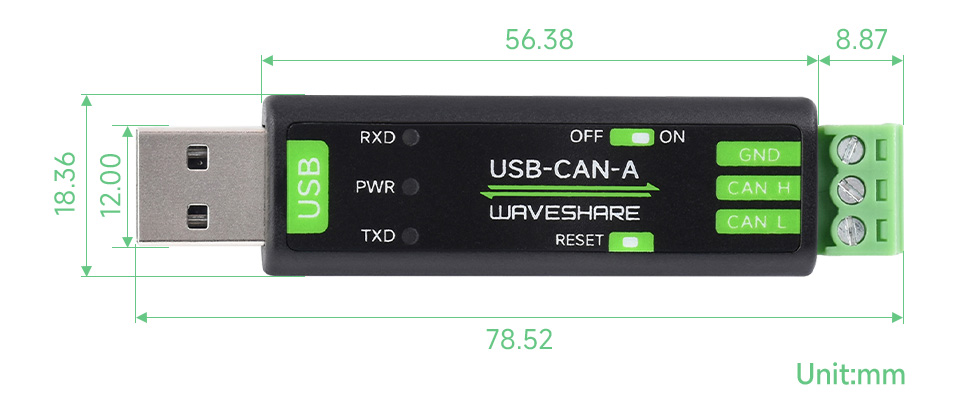
What's in the box?
1 x USB-CAN-A
1 x USB Cable ~1.5m
1 x Screwdriver
Resources

Dedicated Aluminum Heatsink, Corrosion / Oxidation Resisting, Better Heat Dissipation

Matches The Size And Mounting Holes Of The Raspberry Pi 5, With Thermal Pads

1 x Pi5-Active-Cooler-C
1 x Thermal pad (3PCS)
How To Install
Attach The Thermal Pads And Fix The Aluminum Heatsink Via Spring-Loaded Push Pins

* for reference only, the Raspberry Pi 5 and TF card are NOT included.


Adopts Temperature-Controlled Blower Fan, Faster Heat Dissipation, More Durable

* for reference only, the Raspberry Pi 5 is NOT included
Aluminium Alloy Case, With Temperature-Controlled Blower Fan And Aluminium Heatsink
For Better Heat Dissipation

More Details
Adopts Advanced Metal Cutting Processing, With Precise Openings For Sorts Of Connectors, More Convenient For Wiring


The Fins Work Together With The Cooling Fan To Accelerate Heat Dissipation, Ensuring Stable Operation Of The Raspberry Pi 5

What's in the box?
1 x Aluminium Alloy lower plate
1 x Aluminium Alloy upper plate
1 x Cooling fan
1 x Screwdriver
1 x L-form hex socket spanner
1 x Thermal tape 4PCS
1 x Screws pack
The Case Consists Of Upper And Lower Cover Plates, With Thermal Tapes,
Easy To Install


Clear Acrylic Panels, Nice Looking, Dustproof

* for reference only, the Raspberry Pi 5 is NOT included
Precise Openings For Sorts Of Connectors, Supports Installing Official Active Cooler (Not Included)

More Details
Openings For 40PIN GPIO, PCIe, DSI/CSI Interfaces And Airflow Vents On The Top And For RTC Battery Connector/UART Header On The Side, With Power On/Off Button. Easy To Pull & Plug TF Card On The Bottom


* for reference only, please refer to the Package Content for detailed part list
What's in the box?
1 x Nonskid rubber pad (4PCS)
1 x Screwdriver
1 x Screws and standoffs pack
Resources
The Case Consists Of 6 Layers Of Acrylic Panels, Please Install According To The Following Steps


1. Install the short standoffs and screws onto the 1st acrylic panel, please pay attention to the orientation.

2. Install the 5th acrylic panel to the USB ports and Ethernet port of Raspberry Pi 5, and then mount Raspberry Pi 5 on the short standoffs as shown.

3. Fix the Raspberry Pi 5 via long standoffs, then install the 3rd, 4th, and 6th acrylic panels.
4. Install the active cooler on the Raspberry Pi 5, then install the 2nd acrylic panel on the top and fix it via screws.

CH344L | Stable Transmission | Multiple Devices Applicable | Multi-OS Compatible

Features At A Glance
- Adopts original CH344L chip, fast communicating, stable and reliable, better compatibility
- Supports USB to 4-ch isolated RS485, convenient for expanding multiple RS485 industrial serial devices
- Onboard unibody power supply isolation, provides stable isolated voltage, needs no extra power supply for the isolated terminal
- Onboard unibody digital isolation, allows signal isolation, high reliability, strong anti-interference, low power consumption
- Onboard TVS (Transient Voltage Suppressor), effectively suppress surge voltage and transient spike voltage in the circuit, lightningproof & ESD protection
- Onboard self-recovery fuse and protection diodes, ensures the current/voltage stable outputs, provides over-current/over-voltage proof, improves shock proof performance
- Onboard RS485 output terminal 120R resistors, enabled/disabled via DIP switch
- 10 LEDs for indicating the power, device configuration status and transceiver status
- Industrial grade metal case, supports wall-mount & rail-mount installation, solid and beautiful, easy to install
Specifications
| PRODUCT TYPE | Industrial isolated USB to RS485 converter | |
|---|---|---|
| HOST PORT | USB | |
| DEVICE PORT | RS485 | |
| BAUDRATE | 1200bps ~ 460800bps | |
| USB | Operating voltage | 5V |
| Connector | USB-B | |
| Protection | 500mA resettable fuse, output isolation | |
| ISOLATED RS485 | Connector | Screw terminal |
| Direction control | Hardware automatic control | |
| Protection | 600W lightningproof and surge-suppress, 15KV ESD protection (onboard 120R matching resistors) | |
| Transmission mode | Point-to-multipoints (up to 32 nodes, it is recommended to use repeaters for 16 nodes or more) | |
| INDICATORS | PWR | Power indicator, lights up while the USB is connected and voltage is detected |
| ACT | Status indicator, lights up green while the driver is detected. | |
| RXD | RXD indicator, lights up when the device ports send data back | |
| TXD | TXD indicator, lights up when the USB port is sending data | |
| OPERATING ENVIRONMENT | Temperature | -40 ~ 85℃ |
| Humidity | 5%RH ~ 95%RH | |
| OPERATING SYSTEM | Win7/8/8.1/10/11, Mac, Linux, Android | |
Safer Isolated Design
- Onboard unibody power supply isolation, provides stable isolated voltage, needs no extra power supply for the isolated terminal
- Onboard unibody digital isolation, allows signal isolation, high reliability, strong anti-interference, low power consumption

Multiple Protection, Safe And Stable
Onboard TVS (Transient Voltage Suppressor), effectively suppress surge voltage and transient spike voltage in the circuit, lightningproof & ESD protection. Onboard self-recovery fuse and protection diodes, ensures the current/voltage stable outputs, provides over-current/over-voltage proof, improves shock proof performance.

Multi System Support
Supports Mac, Linux, Android, Windows 11 / 10 / 8.1 / 8 / 7, Etc.

Transmission Distance Up To 1.2km
The USB Signal Can Be Converted Into 4 Balanced Differential RS485 Signals And The Transmission Rate Is Stable. The Reliable Speed Is 1200~460800bps, The Transmission Distance Is About 1.2km For RS485, And About 5 Meters For USB

Aluminium Alloy Enclosure
Aluminium Alloy Enclosure With Sand Blasting And Anodic Oxidation,
Solid And Durable, Fashionable And Good Hand Feeling
Wall-Mount & Rail-Mount Support, More Flexible For Industrial Installation


Outline Dimensions

What's in the box?
1 x USB TO 4CH RS485 (B)
1 x Rail-mount buckle
1 x USB type A to type B cable ~1.2m
1 x Screwdriver
Resources
www.waveshare.com/wiki/USB_TO_4CH_RS485_(B)