
WaveShare


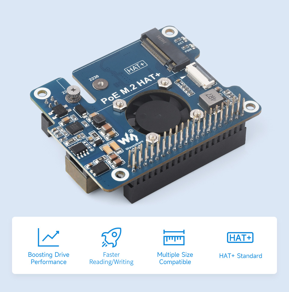
Designed For Raspberry Pi 5, Supports IEEE 802.3af/at Network Standard
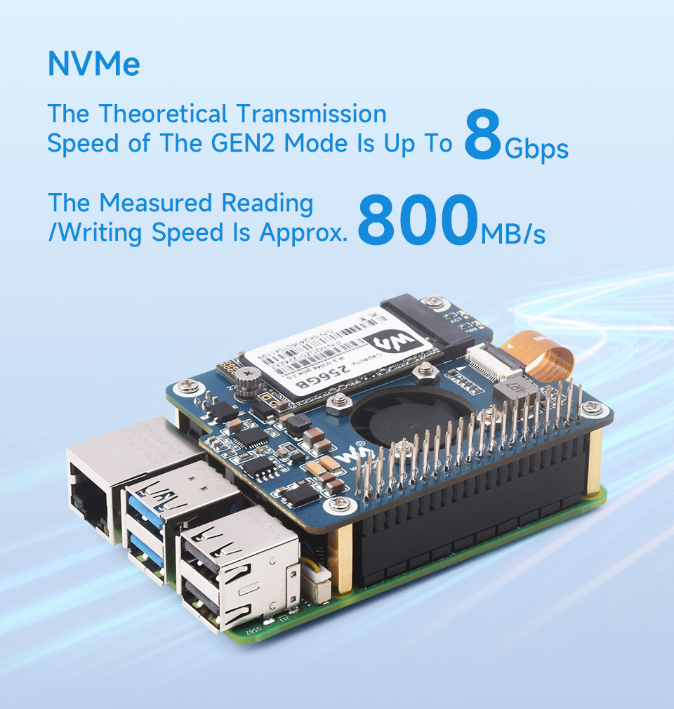
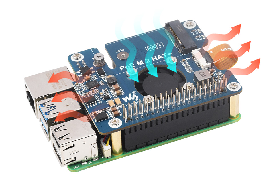
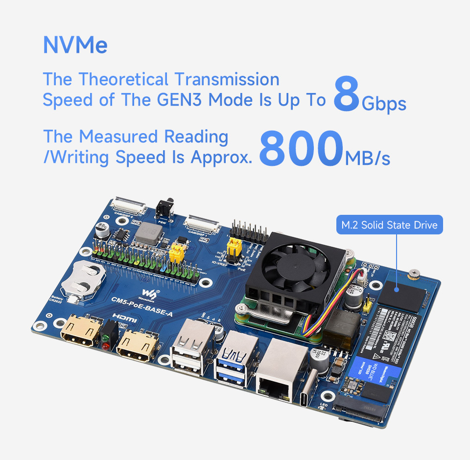
Adapter For NVMe Protocol M.2 Solid State Drive, High-speed Reading/Writing
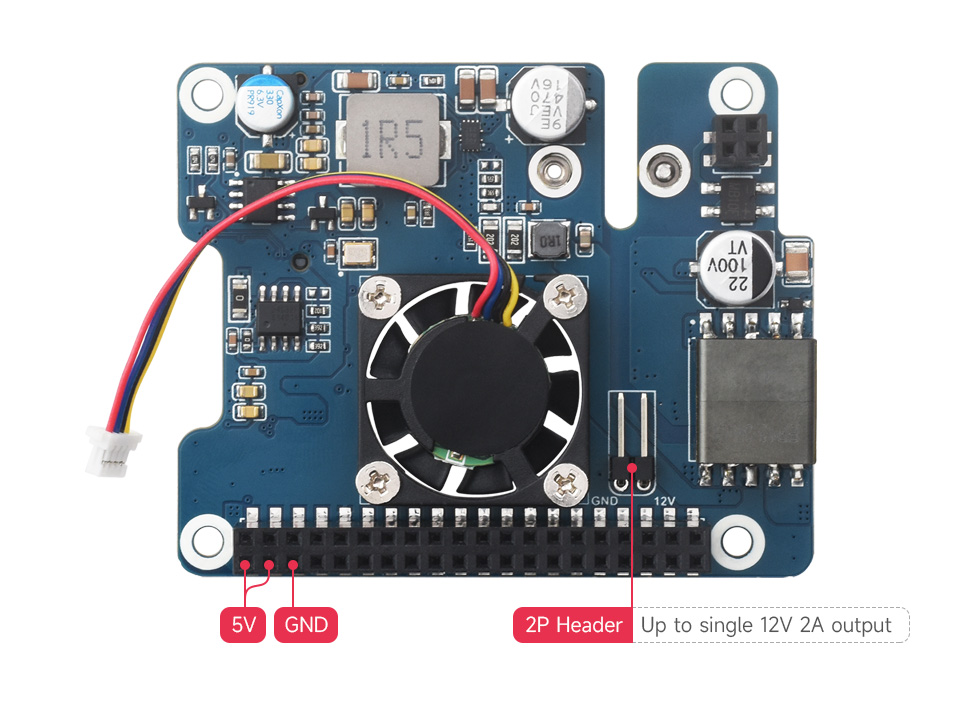
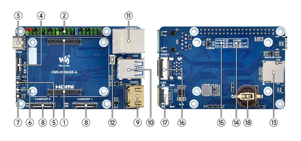
| PoE power input | 37V ~ 57V DC in |
|---|---|
| Power output | GPIO header: 5V 4.5A (MAX) 2P header: 12V 2A (MAX) |
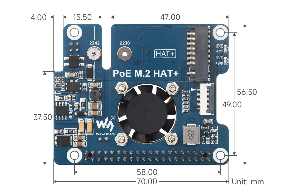
| Dimensions | 56.5 × 70.0mm |
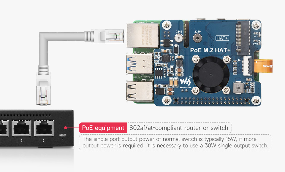
| Network standard | IEEE 802.3af/at PoE |
for reference only, the Raspberry Pi 5 is not included.
Note: Only supports the NVMe Protocol Solid State Drives.
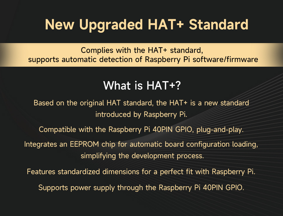
Based on 16PIN PCIe Interface of Raspberry Pi 5.
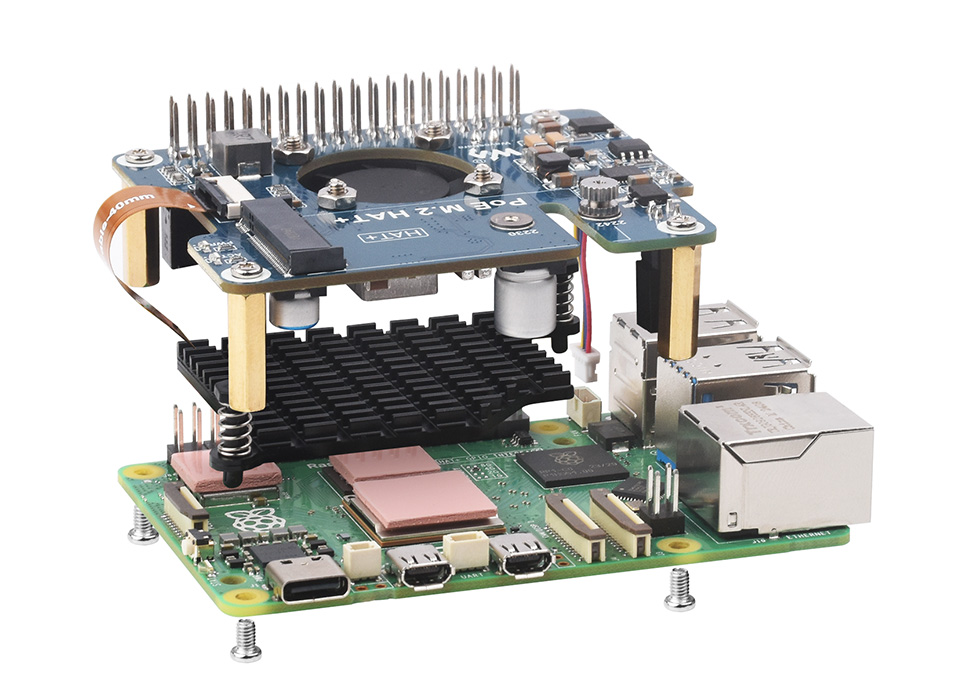
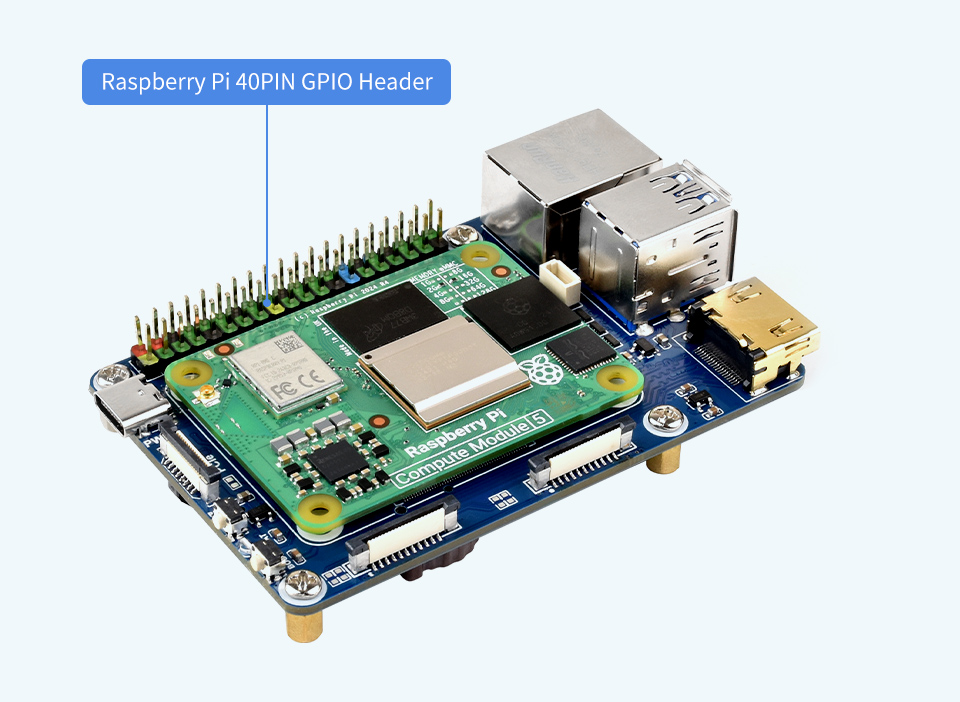
Standard Raspberry Pi 40PIN GPIO stackable header, allows connecting other HATs
for reference only, please refer to the Package Content for detailed part list
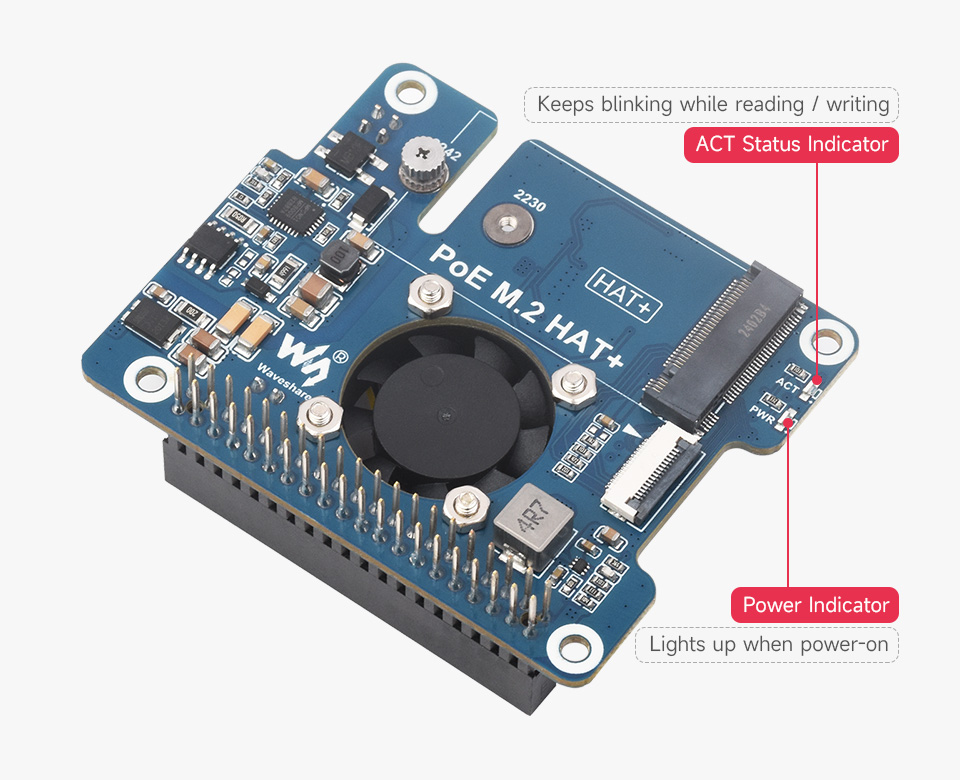
Easy to monitor the Working Status
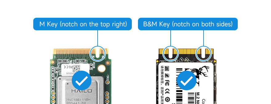
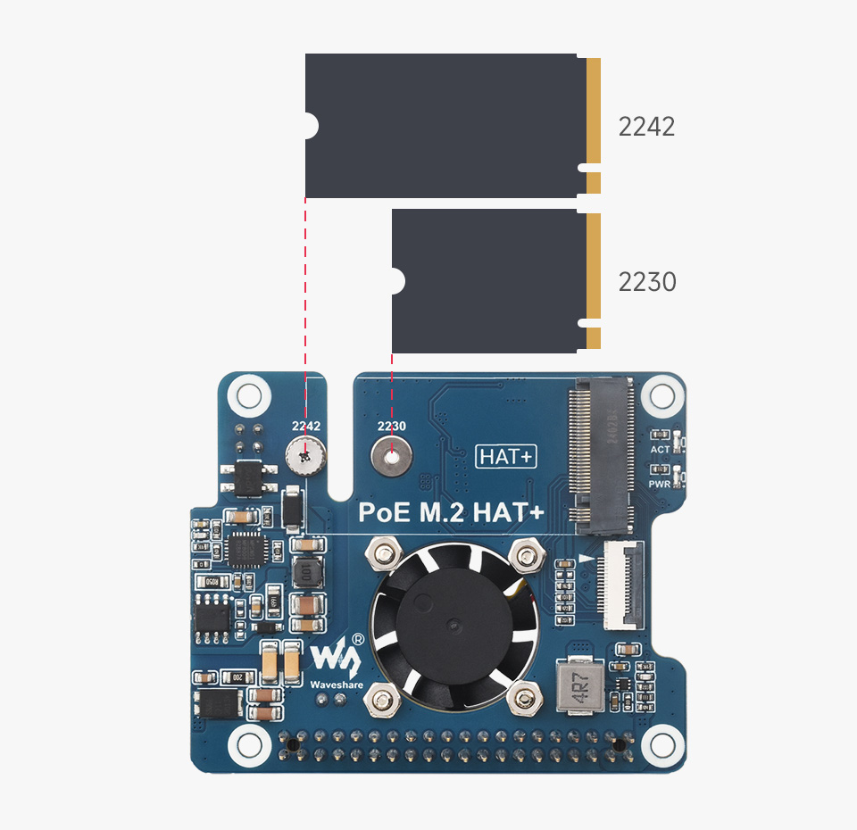
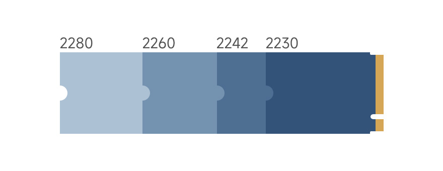
Compatible With 2230/2242 Size M.2 Solid State Drive
Supports Gen2 and Gen3 Modes, Supports Booting PI5 From Solid State Drive
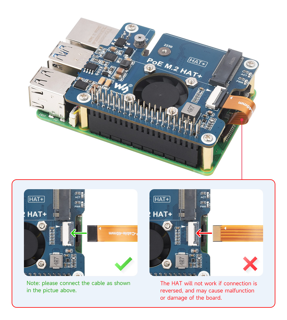
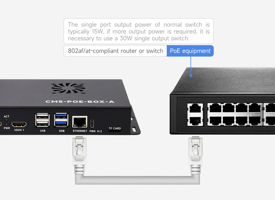
Providing both network connection and power supply for your Raspberry Pi in one cable
5V header provides up to 4.5A output (MAX 25W for 12V+5V total output power)
be able to power extra devices while providing stable power to Raspberry Pi
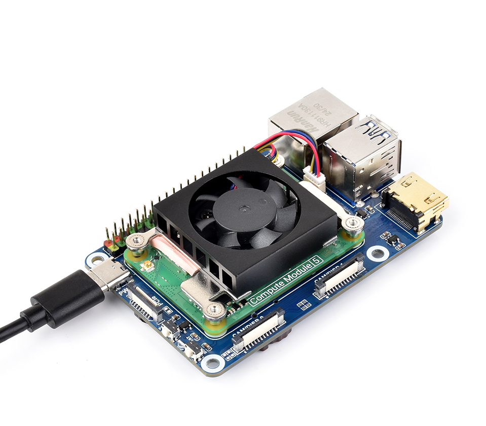
Accelerate Cooling Effect, More Stable Performance
Attach the thermal tapes first, then install the metal heatsink and fix the HAT
for reference only, please refer to the Package Content for detailed part list
1 x PoE M.2 HAT+
1 x Metal heatsink
1 x 16P-Cable-40mm
1 x Thermal tape (3PCS)
1 x Screws pack
You might also need our case made specifically to house this kind of board

long range | short blind zone | stable/accurate/sensitive | indoor/outdoor

This is a TOF-based (time of flight) laser ranging sensor with embedded MCU and ranging algorithm, which is capable of offering up to 25m / 50m measuring range, and ±3cm accuracy. It supports UART or I2C communication bus, features longer measuring distance and higher light interference tolerance capability due to its ultra narrow FOV, suitable for either indoor or outdoor condition. And its ambient light tolerance is up to 100K LUX.
This sensor can be widely used in applications like common distance measuring, robot obstacle avoidance / route planning, as well as drone altitude setting / ceiling detection, and more...

TOF Laser Range Sensor (C)
25m measuring range
| Model | TOF Laser Range Sensor (C) | TOF Laser Range Sensor (D) |
|---|---|---|
| Typical measuring range | 0.05 ~ 25.0m | 0.05m ~ 50.0m |
| Typical measuring accuracy | 0.05 ~ 25m ±3cm | 0.05m ~ 50m ±3cm |
| Wavelength | 905nm | |
| Field of view (FOV) | 1° ~ 2° | |
| Communication interface | Default: UART (3.3V TTL signal level) | |
| I2C (cascading support, the slave address is 0x08+module ID) | ||
| complementary I/O level output (distance parameter is not available in this mode) | ||
| Baudrate | UART: 4.8Kbps ~ 3000Kbps (921.6Kbps by default) | |
| I2C: up to 400Kbps | ||
| Power supply | 4.3 ~ 5.2V | |
| Power consumption | 250mW (UART active output, 5.0V power supply, 50mA current) | |
| Weight | 7.7g | |
| Operating temperature | -10°C ~ 60°C | |
| Dimensions | 22.7mm × 28mm × 13.6mm (L × W × H) | |
long range low cost ranging module
high stability, high accuracy, high sensitivity ranging

UART mode: supports active query output
I2C mode: up to 8x cascades
I/O mode: unable to output distance parameter


Hydraulic Stacking Detection
Connecting with Raspberry Pi (via I2C)

Connecting with Raspberry Pi (via UART)

Connecting with Raspberry Pi (via I/O pins)


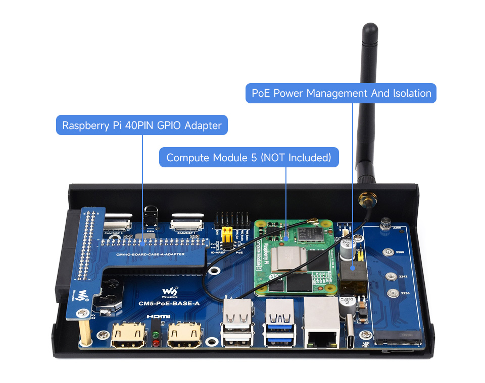
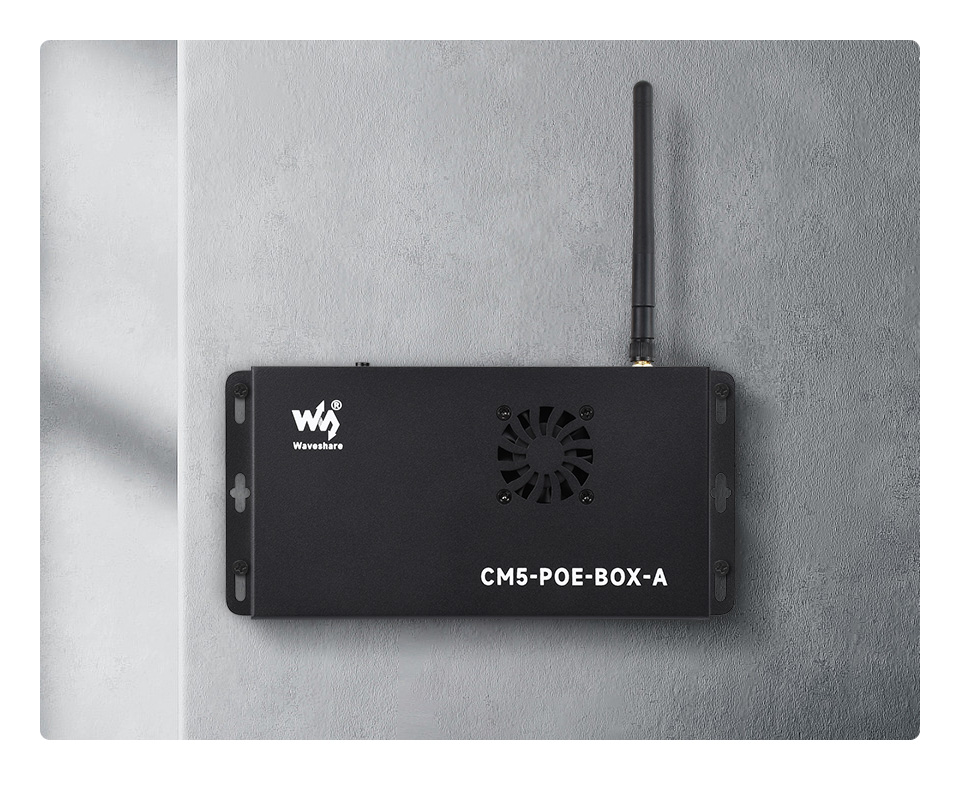
suitable for evaluating the Raspberry Pi CM5 or being integrated into end products
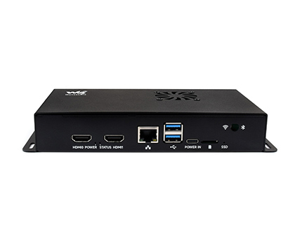
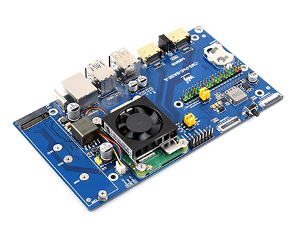
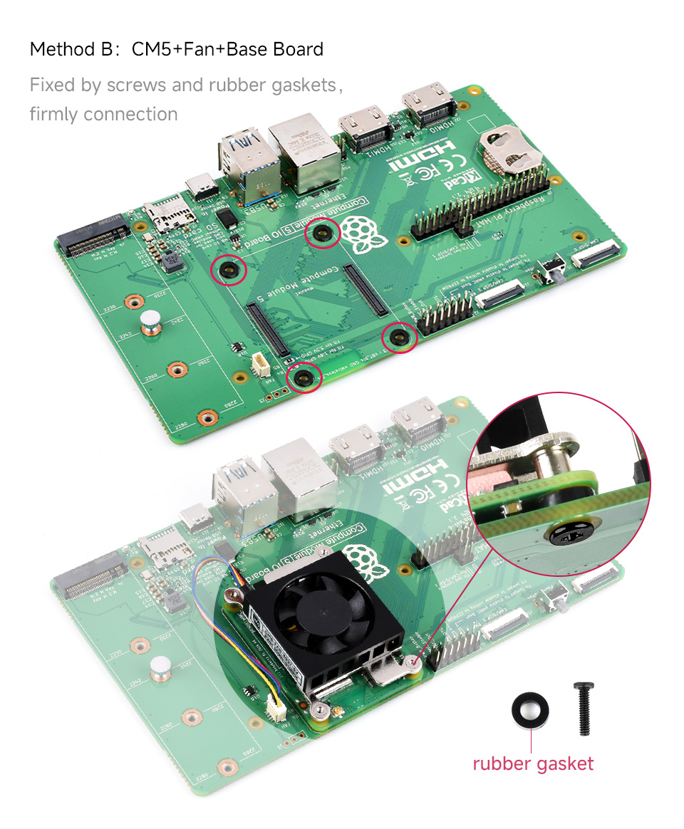
PoE Base Board for all Compute Module 5 Variants
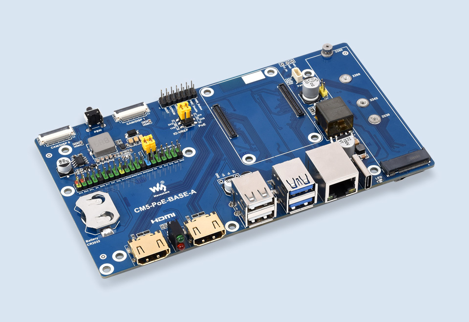
| CM5 socket | suitable for all variants of Compute Module 5 |
|---|---|
| Networking | Gigabit Ethernet RJ45 connector, integrates 802.3af/at-compliant PoE circuit (5V/5A) |
| Connector | Raspberry Pi 40PIN GPIO header |
| USB | USB 3.2 Gen1 × 2 |
| USB 2.0 × 2 | |
| MIPI | 4-lane MIPI interface × 2 (22pin 0.5mm FPC connector) |
| Video | HDMI port × 2, supports 4K output |
| RTC | CR / ML2032 battery holder |
| Storage | TF card slot for Compute Module 5 Lite (without eMMC) variants |
| Fan connector | 5V, JST-SH PWM 4PIN connector |
| NVMe | PCIe Gen2/3 × 1 |
| Power input | 5V 5A |
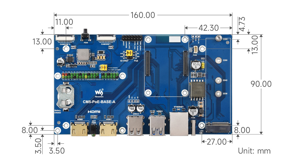
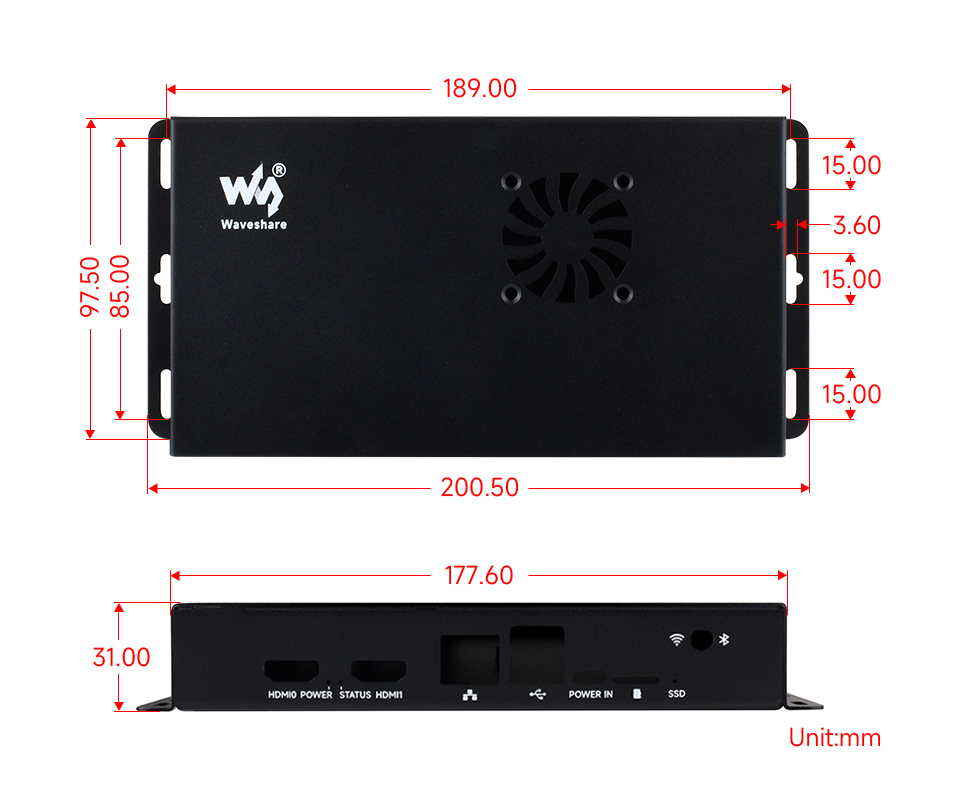
| Dimensions | the base board: 160 × 90 (mm) |
| with metal case: 200.5 × 97.5 × 31.0 (mm) |
Standard CM5 socket and Raspberry Pi 40PIN GPIO header
suitable for all variants of Compute Module 5

Providing both network connection and power supply for your Raspberry Pi in one cable

Faster reading/writing speed compared to the TF card slot of Raspberry Pi, greatly improving reading/writing efficiency of the system or files, support booting Raspberry Pi from NVMe Solid State Drive
* for reference only, please refer to the Package Content for detailed part list


Note: Only supports the NVMe Protocol Solid State Drives.
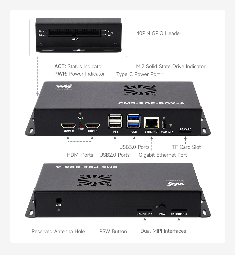
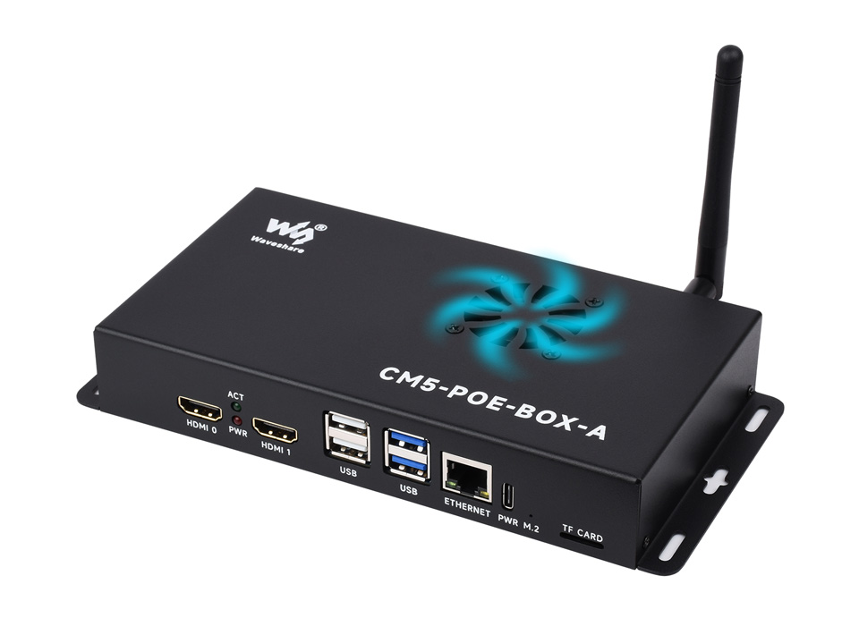
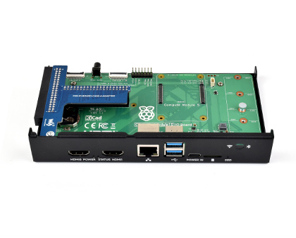
Onboard connectors including MIPI / M.2 / HDMI / USB / ETH / TF Card Slot

Ideal for Raspberry Pi applications with multiple peripheral requirements, or other industrial context

- for reference only, please refer to the Package Content for detailed part list

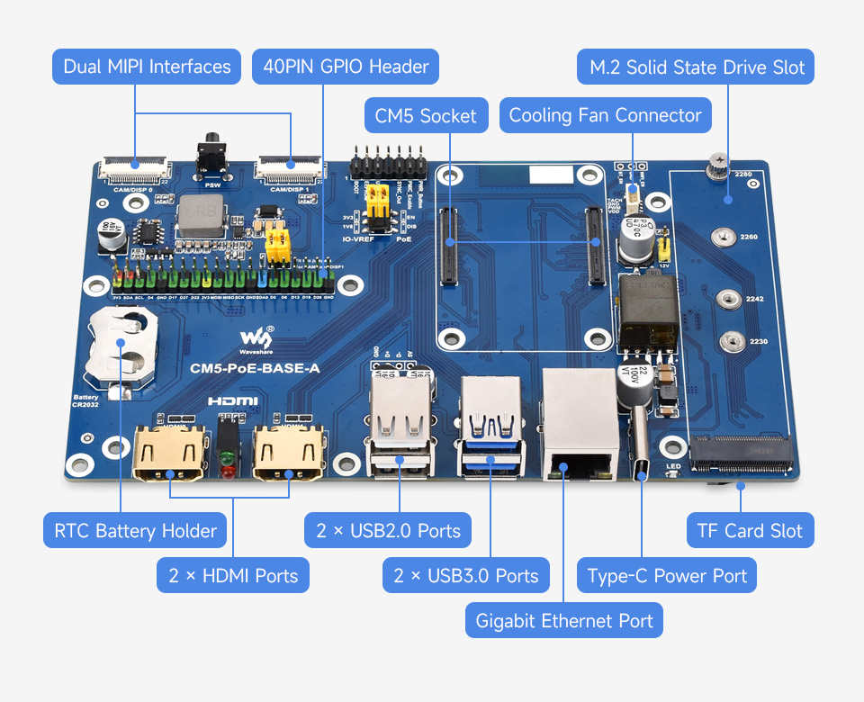
- CM5 socket
Suitable for all variants of Compute Module 5 - USB Type-C power supply / programming
5V/5A power supply, also allows burning system image into Compute Module 5 variants - M.2 Solid State Drive indicator
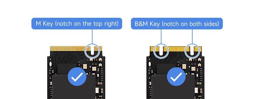
Keeps blinking while reading/writing - M.2 M key
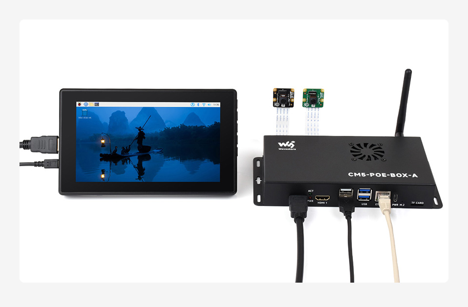
Compatible with 2280/2260/2242/2230 NVMe drives or AI accelerator module - Dual MIPI interfaces
for connecting DSI LCDs or CSI cameras - PSW button
power button - 40PIN GPIO header
for connecting various HATs - RTC battery holder
Supports CR/ML2032 button cell - HDMI ports
2x HDMI ports, supports dual 4K output - Status indicators
ACT: Raspberry Pi operating status indicator
PWR: Raspberry Pi power indicato
- USB2.0 ports
2x USB2.0 ports, for connecting sorts of USB devices - USB 3.2 Gen1 ports
2x USB 3.2 Gen1 high-speed ports, supports 5Gbps synchronous operation - Gigabit Ethernet connector
Gigabit Ethernet RJ45 with PoE support - FAN connector
for connecting cooling fan - Misc configurations
for extending other functions - IO-VREF/PoE selection
CM5 IO logic level: 3.3V or 1.8V
PoE: enable (EN) or disable (DIS) - CAM1 and DISP1 I2C bus
fit the jumpers when using CAM1 or DISP1 - TF card slot (bottom side)
insert a TF card with pre-burnt system, to start up Compute Module 5 Lite
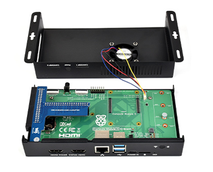
PoE Base Board
What's in the box?
1 x CM5-PoE-BASE-A
1 x Screws pack
Resources

suitable for evaluating the Raspberry Pi CM5 or being integrated into end products
PoE Base Board for all Compute Module 5 Variants

| CM5 socket | suitable for all variants of Compute Module 5 |
|---|---|
| Networking | Gigabit Ethernet RJ45 connector, integrates 802.3af/at-compliant PoE circuit (5V/5A) |
| Connector | Raspberry Pi 40PIN GPIO header |
| USB | USB 3.2 Gen1 × 2 |
| USB 2.0 × 2 | |
| MIPI | 4-lane MIPI interface × 2 (22pin 0.5mm FPC connector) |
| Video | HDMI port × 2, supports 4K output |
| RTC | CR / ML2032 battery holder |
| Storage | TF card slot for Compute Module 5 Lite (without eMMC) variants |
| Fan connector | 5V, JST-SH PWM 4PIN connector |
| NVMe | PCIe Gen2/3 × 1 |
| Power input | 5V 5A |
| Dimensions | the base board: 160 × 90 (mm) |
| with metal case: 200.5 × 97.5 × 31.0 (mm) |
Standard CM5 socket and Raspberry Pi 40PIN GPIO header
suitable for all variants of Compute Module 5
Providing both network connection and power supply for your Raspberry Pi in one cable
Faster reading/writing speed compared to the TF card slot of Raspberry Pi, greatly improving reading/writing efficiency of the system or files, support booting Raspberry Pi from NVMe Solid State Drive

* for reference only, please refer to the Package Content for detailed part list
Note: Only supports the NVMe Protocol Solid State Drives.
Onboard connectors including MIPI / M.2 / HDMI / USB / ETH / TF Card Slot
Each cut-out is completely aligned with the connector
Comes with cooling fan, combined with the airflow vent, better heat dissipation
Wall mount holes on two sides, handy for mounting
Ideal for Raspberry Pi applications with multiple peripheral requirements, or other industrial context
* for reference only, please refer to the Package Content for detailed part list
- CM5 socket
Suitable for all variants of Compute Module 5 - USB Type-C power supply / programming
5V/5A power supply, also allows burning system image into Compute Module 5 variants - M.2 Solid State Drive indicator
Keeps blinking while reading/writing - M.2 M key
Compatible with 2280/2260/2242/2230 NVMe drives or AI accelerator module - Dual MIPI interfaces
for connecting DSI LCDs or CSI cameras - PSW button
power button - 40PIN GPIO header
for connecting various HATs - RTC battery holder
Supports CR/ML2032 button cell - HDMI ports
2x HDMI ports, supports dual 4K output - Status indicators
ACT: Raspberry Pi operating status indicator
PWR: Raspberry Pi power indicato
- USB2.0 ports
2x USB2.0 ports, for connecting sorts of USB devices - USB 3.2 Gen1 ports
2x USB 3.2 Gen1 high-speed ports, supports 5Gbps synchronous operation - Gigabit Ethernet connector
Gigabit Ethernet RJ45 with PoE support - FAN connector
for connecting cooling fan - Misc configurations
for extending other functions - IO-VREF/PoE selection
CM5 IO logic level: 3.3V or 1.8V
PoE: enable (EN) or disable (DIS) - CAM1 and DISP1 I2C bus
fit the jumpers when using CAM1 or DISP1 - TF card slot (bottom side)
insert a TF card with pre-burnt system, to start up Compute Module 5 Lite
PoE Base Board

PoE Mini-Computer Kit
1 x CM5-PoE-BASE-A
1 x CM4-IO-BOARD-CASE-A-ADAPTER
1 x CM5-FAN-4010-5V
1 x 27W USB-C power supply
1 x Screwdriver
1 x Antenna connector rubber plug
1 x Button cap
1 x Screws pack

Suitable for evaluating the Raspberry Pi CM5 or being integrated into end products
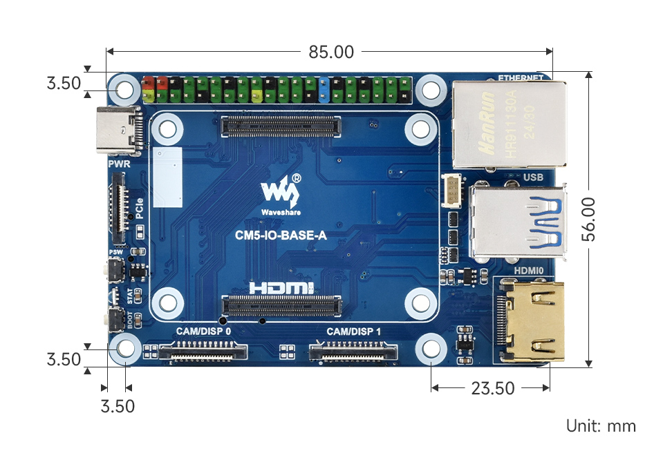
Powerful functions in a credit card sized body
| CM5 socket | suitable for all variants of Compute Module 5 |
|---|---|
| Networking | Gigabit Ethernet RJ45 connector |
| Connector | 16PIN PCIe (PCIe Gen2/3 x1) |
| Raspberry Pi 40PIN GPIO header | |
| USB | USB 3.2 Gen1 Type A × 2, USB 2.0 via 6PIN 1mm FFC connector × 2 |
| MIPI | 4-lane MIPI interface × 2 (22pin 0.5mm FFC connector) |
| Video | HDMI port × 2 (including one port via FFC connector), supports dual 4K outputs |
| Storage | TF card slot for Compute Module 5 Lite (without eMMC) variants |
| Fan header | 5V, 4PIN JST-SH PWM connector |
| Power input | DC 5V 5A |
| Dimensions | 85 × 56mm |
| CM5 Base Board | Interface count and specifications | |||||||||||
|---|---|---|---|---|---|---|---|---|---|---|---|---|
| PoE | Gigabit ETH | 40PIN GPIO | PCIe | USB① | MIPI | HDMI | RTC | Fan Header② | Power Input | Features | ||
 mini Base A | ×1 | √ | 16PIN PCIe | 3.0×2 2.0×2 | ×2 | ×2 | ML/CR1220 | √ | 5V | mini size | ||
 PoE Base | √ | ×1 | √ | M.2 M | 3.0×2 2.0×2 | ×2 | ×2 | ML/CR1220 | √ | 5V | USB×4 | |
 Raspberry Pi official | ③ | ×1 | √ | M.2 M | 3.0×2 | ×2 | ×2 | ML/CR1220 | √ | 5V | Official IO base board | |
| Note | ① USB 3.0 is equivalent to USB 3.2 Gen1. ② Unless otherwise specified, the Fan header usually is JST-SH type connector. ③ There's PoE header only on the Raspberry Pi official IO board without PoE circuit, which means additional PoE module is required for the official IO board to enable PoE feature. Unless otherwise specified, the PoE feature here stands for integrating 802.3af-compliant PoE circuit (5V/2.5A). | |||||||||||
Standard CM5 socket and color-coded Raspberry Pi 40PIN GPIO header
Suitable for Compute Module 5 Lite/eMMC series module
Onboard multiple connectors, more convenient to use
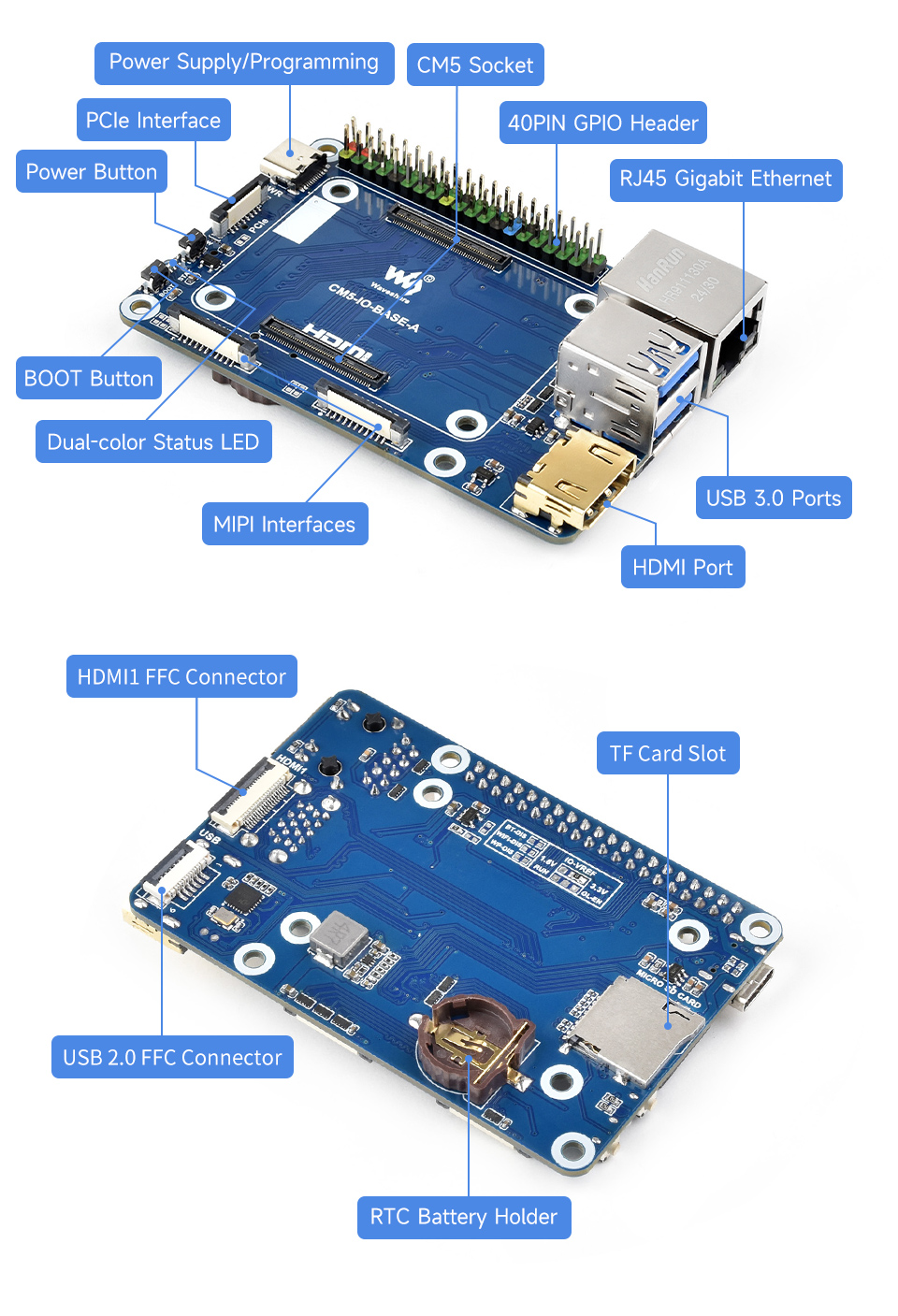
- CM5 socket
suitable for all variants of Compute Module 5 - 40PIN GPIO header
for connecting various HAT / HAT+ modules - Power input/Programming
5V / 5A power supply, or used for eMMC burning - PCIe interface
for connecting various PCIe expansion boards - PSW Power button
Long press to force power off, short press to soft power off or on - STAT LED
Dual-color status LED - BOOT button
Press before powering on and release after powering on to enter the burning mode - Dual MIPI interfaces
for connecting DSI displays and CSI cameras - HDMI0 connector
HDMI0 port, supports 4K output - USB 3.2 Gen1 ports
2x USB 3.2 Gen1 high-speed ports, supports 5Gbps synchronous operatio
- RJ45 Gigabit Ethernet port
Supports 10M / 100M / 1000M network access - 4PIN JST-SH PWM Fan header
for connecting cooling fan, 5V power supply - TF card slot
for connecting a TF card with pre-burnt image (Lite variant ONLY) - IO-VREF selection
CM5 IO logic level: 3.3V (default) or 1.8V - Other function pins
WIFI / BT hardware disable or write protection - HDMI1 FFC connector
HDMI1 port, supports 4K output, can be connected through an adapter - USB 2.0 FFC connector
can be connected through an adapter - RTC battery holder
Supports CR / ML1220 button cell
1 x Screws pack

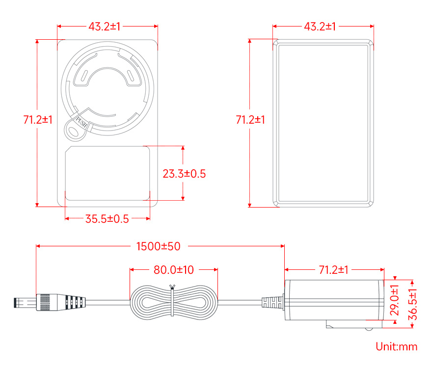
DC jack output, OD 5.5mm, ID 2.1mm
| Plug type | EU |
|---|---|
| Specifications | 1.2m cable, 5.5 / 2.1mm DC jack |
| Protection | Short circuit / Over voltage / Over current |
| Input | AC 100~240V 50 / 60Hz, low idle standby power consumption |
| Output | DC 24V 1.5A, low ripple |
| Safety Certifications | UL / CUL, CE, TUV, SAA, GS |
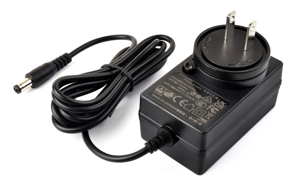
What's in the box?
1 x PSU-24V1.5A-5.5-2.1-US

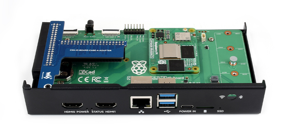
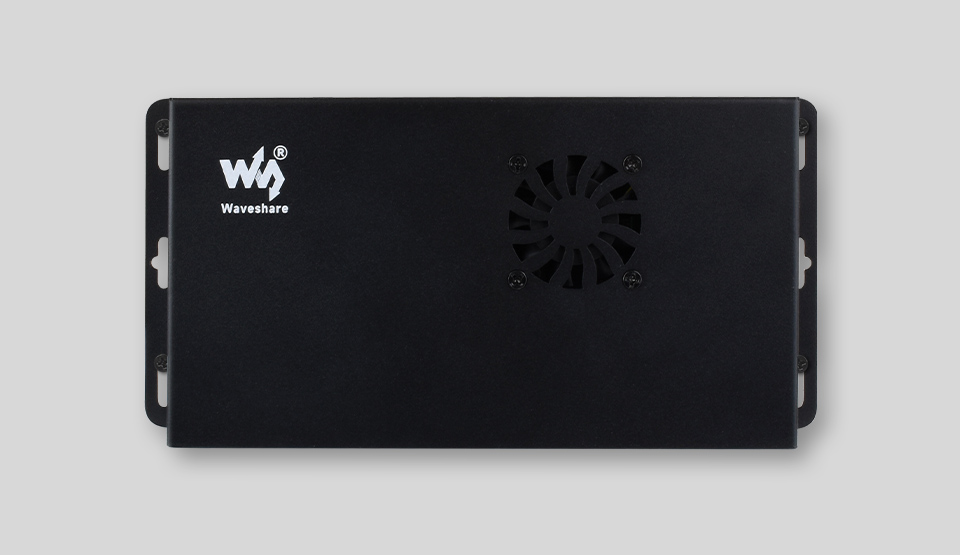
Designed for Raspberry Pi official Compute Module 5 IO Board
Mini computer chassis, robust and dust-proof, nice looking
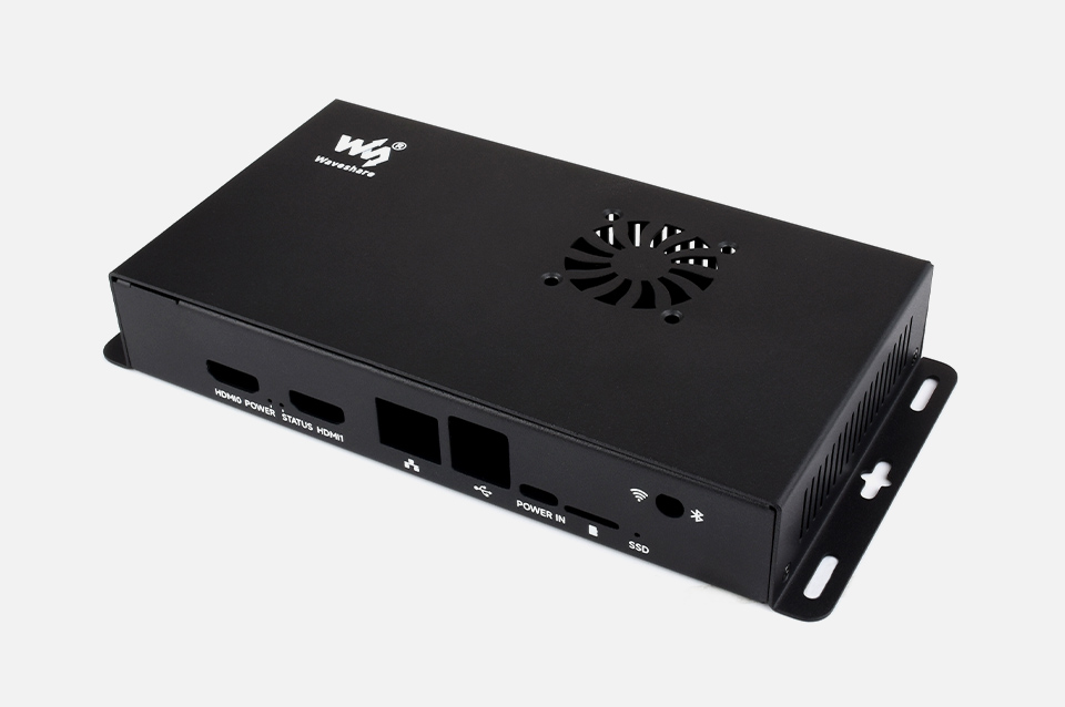
Make it easy to build your own Raspberry Pi CM5 mini PC
* for reference only, please refer to the Package Content for detailed part list
The standard 40PIN GPIO header is still available, making it easy to connect sorts of HATs
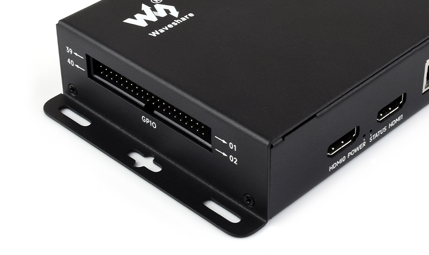
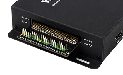
Each cut-out is completely aligned with the connector
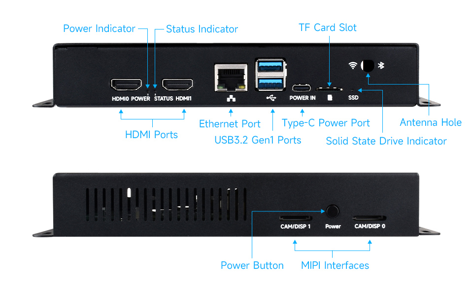
Comes with cooling fan, combined with the airflow vent, better heat dissipation
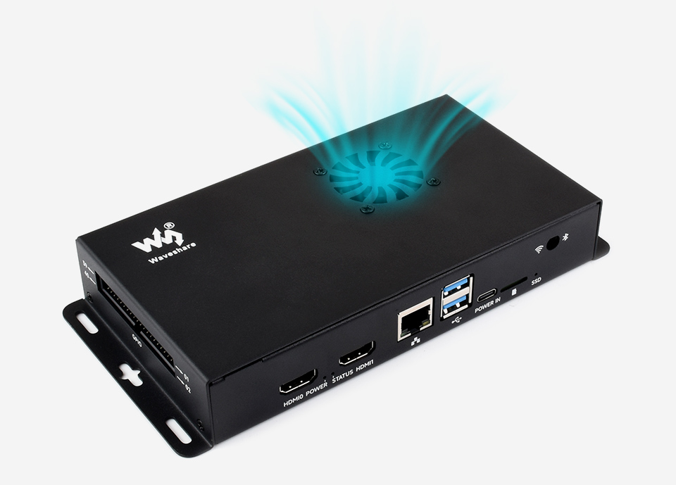
Wall mount holes on two sides, handy for mounting
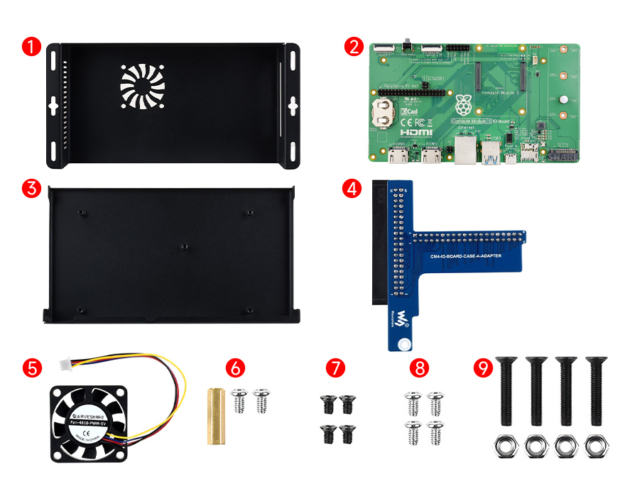
Prepare the accessories as shown above
- Connect the ④ GPIO adapter board to the ② Compute Module 5 IO Board first, and fix them with ⑥ standoff and screws.
2. Fix the ② Compute Module 5 IO Board and the ③ bottom cover via ⑧ screws.
3. Use the ⑨ screws and nuts to install the ⑤ cooling fan to the top cover of the case, then connect the 4PIN fan header to the fan connector of the CM5 IO Board as above.
4. Fix the top cover and bottom cover via ⑦ screws.
* for reference only, the ② Compute Module 5 IO Board is NOT included
1 x Metal case (top and bottom)
1 x 40PIN GPIO adapter
1 x CM5-FAN-4010-5V
1 x Antenna connector rubber plug
1 x Button cap
1 x Screwdriver
1 x Screws pack

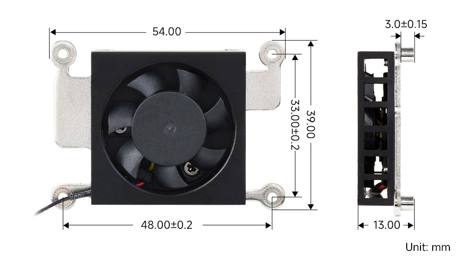
Low noise, with thermal tapes
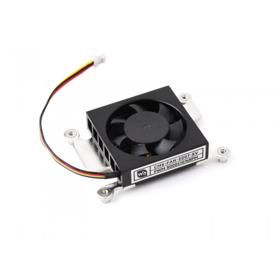
| Rated power | 1W (5V, 0.2±0.02A) |
|---|---|
| Rated speed | 5000±10%RPM |
| General | Low-profile, PWM speed adjustment |
| Interface | 4-wire PWM speed-adjustable fan header |
| Cable length | 90±10mm |
| Dimensions | 54×39×13mm |
Matching with the CM5 on size and mounting holes, fast heat dissipation
No hindrance to the antenna
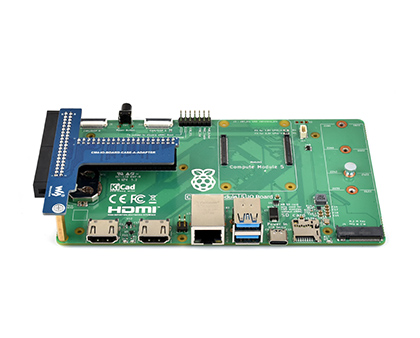
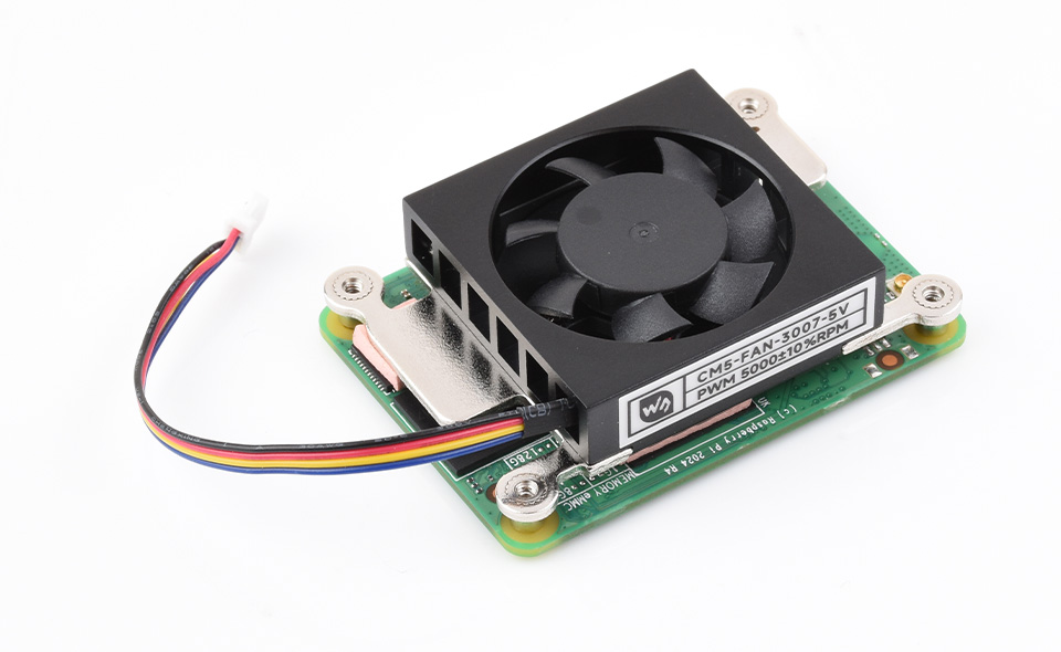
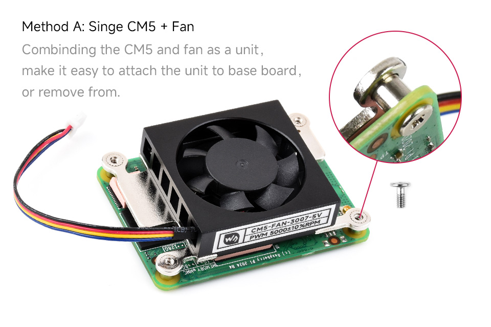
Compute Module 5 IO Board

1. Attach thermal tapes onto the CM5
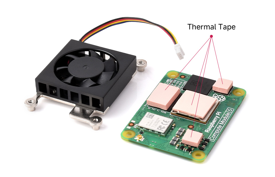
2. Fix the screws as the pictures show
1 x CM5-FAN-3007-5V
1 x Screwspack and thermal tapes

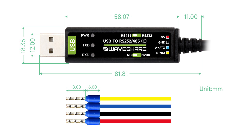
USB to RS232 Or USB to RS485
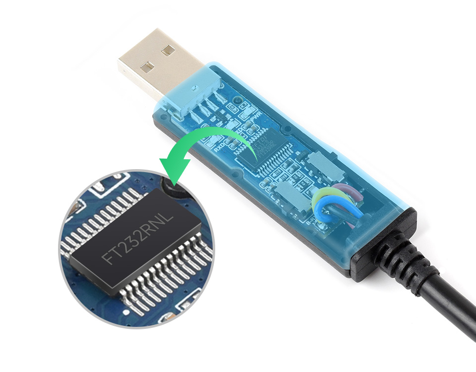
FT232RNL | 2m cable | Stable Transmission | Multi-device Applicable | Multi-OS Compatible
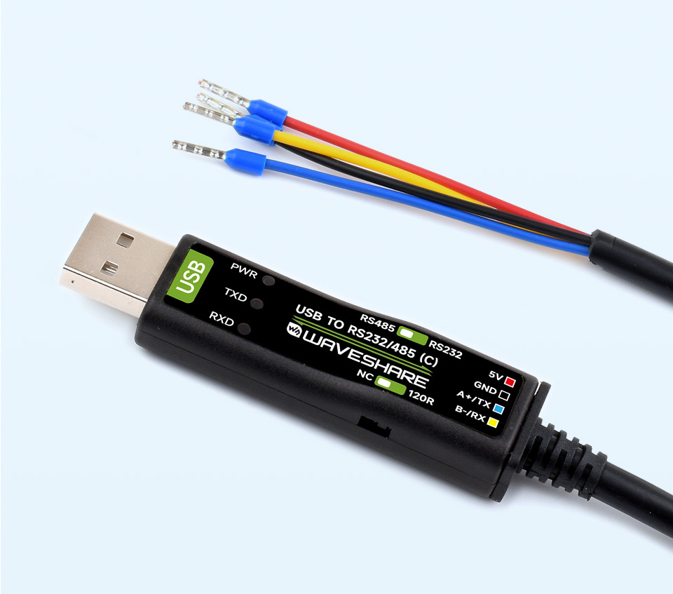
This product is a USB to RS232 / RS485 serial cable, adopts original FT232RNL chip. Onboard power supply and signal indicators, supports 3.3V / 5V level and RS232 / RS485 communication switching. Built-in self-recovery fuse, ESD and IO protection diode circuits, etc.
| PRODUCT TYPE | USB to RS232/485 serial cable | |
|---|---|---|
| Chip | Original FT232RNL chip | |
| Host port | USB | |
| Device port | RS232 / RS485 (switchable) | |
| USB | Connector | USB-A |
| Protection | Self-recovery fuse, ESD protection | |
| RS232 | Connector | 4PIN cable with female crimp connector |
| Protection | TVS tube, surge-suppress and ESD protection | |
| Transmission mode | Point-to-point | |
| Baud rate | 300bps ~ 921600bps | |
| RS485 | Connector | 4PIN cable with female crimp connector |
| Protection | 200W lightningproof, surge-suppress and ESD protection | |
| Transmission mode | Point-to-multipoints | |
| Baud rate | 300bps ~ 921600bps | |
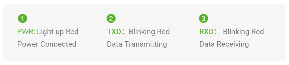
| LED indicators | PWR | Power indicator, lights up when there is USB connection and voltage is detected |
| TXD | TX indicator, lights up when the USB port sends data | |
| RXD | RX indicator, lights up when the device port sends data back | |
| Cable | Black, PVC sheath, 2m cable length | |
Onboard original FT232RNL chip, providing better stability and compatibility
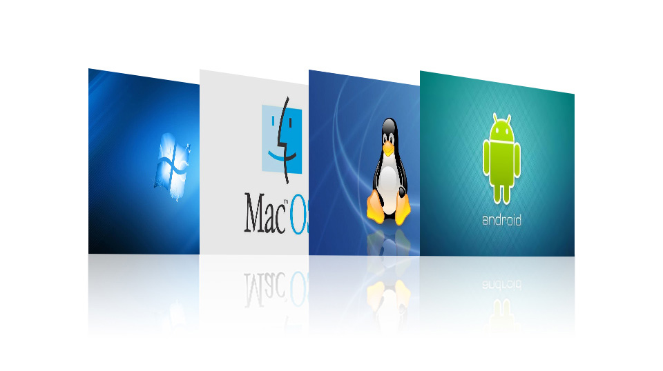
Supports Mac, Linux, Android, Win11/10/8.1/8/7, etc.
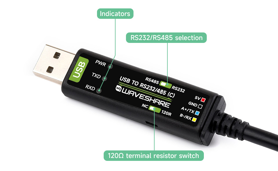

| 5V | 5V output for external devices |
|---|---|
| GND | Ground |
| A+/TX | RS485 differential signal positive A+ / RS232 TXD |
| B-/RX | RS485 differential signal negative B- / RS232 RXD |

NVIDIA Jetson Nano Developer Kit is a small, powerful computer that lets you run multiple neural networks in parallel for applications like image classification, object detection, segmentation, and speech processing. All in an easy-to-use platform that runs in as little as 5 watts.
Jetson Nano delivers 472 GFLOPS for running modern AI algorithms fast, with a quad-core 64-bit ARM CPU, a 128-core integrated NVIDIA GPU, as well as 4GB LPDDR4 memory. It runs multiple neural networks in parallel and processes several high-resolution sensors simultaneously.
Jetson Nano is also supported by NVIDIA JetPack, which includes a board support package (BSP), CUDA, cuDNN, and TensorRT software libraries for deep learning, computer vision, GPU computing, multimedia processing, and much more. The SDK also includes the ability to natively install popular open source Machine Learning (ML) frameworks such as TensorFlow, PyTorch, Caffe / Caffe2, Keras, and MXNet, enables the developers to integrate their favorite AI model / AI framework into products fast and easily.
Upgraded 2-lanes CSI, instead of the previous 1-lane, easily play around with binocular vision
Introduction
- Core module socket
- M.2 Key E connector
- PoE pins: PoE module is not included
- 40PIN GPIO header
- Micro USB port: for 5V power input or for USB data transmission
- Gigabit Ethernet port: 10/100/1000Base-T auto-negotiation, supports PoE if external PoE module is connected
- 4x USB 3.0 port
- HDMI output port
- DisplayPort connector
- DC jack: for 5V power input
- 2x MIPI CSI camera connector
| GPU | 128-core Maxwell |
|---|---|
| CPU | Quad-core ARM A57 @ 1.43 GHz |
| Memory | 4 GB 64-bit LPDDR4 25.6 GB/s |
| Storage | 16GB eMMC |
| Video Encoder | 4K @ 30 | 4x 1080p @ 30 | 9x 720p @ 30 (H.264/H.265) |
| Video Decoder | 4K @ 60 | 2x 4K @ 30 | 8x 1080p @ 30 | 18x 720p @ 30 (H.264/H.265) |
| Camera | 2x MIPI CSI-2 DPHY lanes |
| Connectivity | Gigabit Ethernet, M.2 Key E expansion connector |
| Display | HDMI and DP |
| USB | 4x USB 3.0, USB 2.0 Micro-B |
| Extension Interfaces | GPIO, I2C, I2S, SPI, UART |
What's in the box?
1 x IMX219-77 Camera
1 x 32GB USB drive
1 x Cooling fan
1 x USB cable (~1.2m)
1 x Ethernet cable (~1.5m)
1 x 5V 4A power adapter

Resources
Wiki: JETSON-NANO-DEV-KIT
Nvidia help docs
Introduction to Jetson Developer Kits And Modules

Please note: You will need to buy a different CSI cable for use with RPi 5 or ZERO.
850nm wavelengths specification of an infrared LED is recommended for the Camera.
Features
- Raspberry Pi Night Vision Camera, supports all revisions of the Pi
- 5 megapixel OV5647 sensor
- Camera specifications
- CCD size : 1/4inch
- Aperture (F) : 2.9
- Focal Length : 3.29MM
- Diagonal : 72.4 degree
- Sensor best resolution : 1080p
- 4 screw holes
- Used for attachment
- Provides 3.3V power output
- Supports connecting infrared LED and/or fill flash LED
- Dimension : 25mm x 24mm x 6mm
Raspberry Pi 2/3/4 ribbon cable included
Resources:
Getting started with PiCamera
Development resources:user manual, etc.
Download: www.waveshare.com/wiki/RPi_Camera_(E)

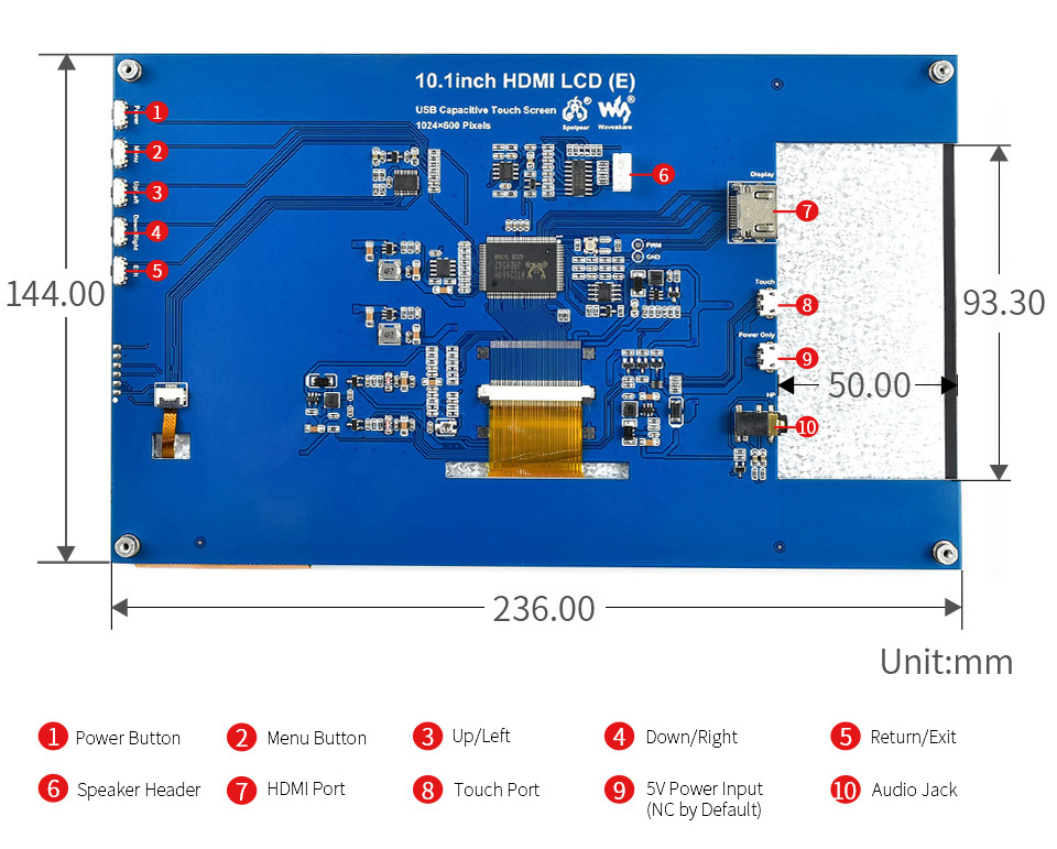
- 1024×600 high resolution
- Resistive touch control
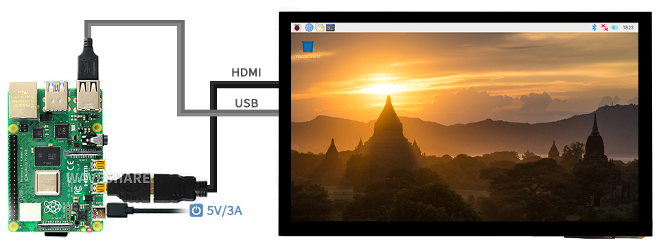
- Compatible and Direct-connect with any revision of Raspberry Pi (except the Pi 1 model B or Pi Zero, which requires an HDMI cable)
- Drivers provided (works with your own Raspbian/Ubuntu directly)
- Also works as a computer monitor, in this case, touch panel is unavailable and HDMI cable is required
- HDMI interface for displaying, no I/Os required (however, the touch panel still needs I/Os)
- Backlight can be turned off to lower power consumption
Interface
| PIN NO. | SYMBOL | DESCRIPTION |
|---|---|---|
| 1, 17 | 3.3V | Power positive (3.3V power input) |
| 2, 4 | 5V | Power positive (5V power input) |
| 3, 5, 7, 8, 10, 11, 12, 13, 15, 16, 18, 24 | NC | NC |
| 6, 9, 14, 20, 25 | GND | Ground |
| 19 | TP_SI | SPI data input of Touch Panel |
| 21 | TP_SO | SPI data output of Touch Panel |
| 22 | TP_IRQ | Touch Panel interrupt, low level while the Touch Panel detects touching |
| 23 | TP_SCK | SPI clock of Touch Panel |
| 26 | TP_CS | Touch Panel chip selection, low active |
External Dimensions

What's in the box?
1 x 10.1inch Resistive Touch Screen
Resources


Device & System Support

Supports Ubuntu / Kali / WIN10 IoT, single point touch, driver free
Supports Retropie, driver free
Supports all versions of Raspberry Pi

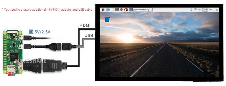
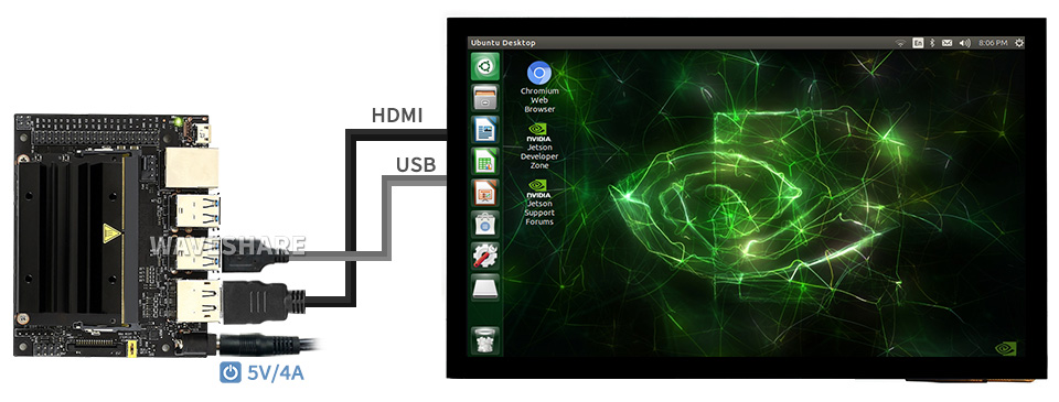
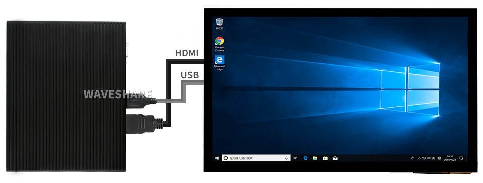
Connection Examples
Raspberry Pi 3/4


Raspberry Pi ZERO W/WH

Jestson Nano

Mini PC

Appearance and Dimensions

What's in the box?
1 x 7.9inch Capacitive Touch Screen
- List of adapters included
- HDMI cable x1
- USB A to Micro-B cable x1
- HDMI Adapter (B) x1
- USB Adapter (B) x1
- HDMI Adapter (C) x1
- USB Adapter (C) x1
- Screws pack x1

Resources

Clear acrylic panels, with customized key cap and a neat design for your Raspberry Pi Pico.
Features
Customized Key Cap, Comfortable And Handy Touch.
Elevated Top Panel, Keeping Enough Space For Pin headers And USB Port.
Reversed Notch For SWD Debugging Pins.
What's in the box ?
1 x Acrylic top panel and bottom panel
1 x Key cap
1 x Screws and standoffs pack
1 x Screwdriver


Size 10.1" | Resolution 1024×600 1024×600 | Display Port HDMI HDMI | Display Panel IPS IPS | Viewing Angle 170° 170° |
Touch Type Capacitive Capacitive | Touch Points 10-Points 10-Points | Touch Port USB USB | Touch Panel Toughened Glass Toughened Glass | Touch Panel Tech Fully Laminated Fully Laminated |
OSD Menu Brightness/Contrast Brightness/Contrast | Audio Output1 3.5mm Jack 3.5mm Jack | Audio Output2 4PIN Header 4PIN Header | Gaming Xbox360/PS4/Switch Xbox360/PS4/Switch |
Supports Raspbian, 10-points touch, driver free
Supports Ubuntu / Kali / WIN10 IoT, single point touch, driver free
Supports Retropie, driver free
Supports all versions of Raspberry Pi
Working With Raspberry Pi 4
Working With Raspberry Pi Zero W
Working With AI Computer Jetson Nano
Working With Mini PC
IPS Panel
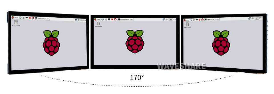

1) up to 10-points touch, depending on the operating system. 2) up to 6H hardness toughened glass panel. 3) fully laminated screen, better display experience, dust-proof.


* audio output from earphone jack and speaker header.
1 x HDMI cable
1 x HDMI to Micro HDMI Adapter
1 x USB-A to Micro-B cable
Resources


Suitable For LPWA, SMA Male Connector, 2dBi
Outline Dimensions
Specifications
- NETWORK SUPPORT LPWA
- GAIN 2dBi
- FREQUENCY RANGE 423~433MHz, 833~903MHz
- CONNECTOR SMA male connector
- OUTPUT IMPEDANCE 50Ω
- ANTENNA LENGTH 11cm
- SWR ≤2.0
- MATERIAL ABS
- POLARIZATION Vertical
- COLOUR Black
What's in the box?
1 x 2dBi LPWA LoRa Antenna


Features At A Glance
- Support USB to RS485 bidirectional conversion
- Fast communication, stable and reliable, better compatibility
- Onboard TVS (Transient Voltage Suppressor), effectively suppress surge voltage and transient spike voltage in the circuit, lightning proof & anti-electrostatic
- Onboard resettable fuse and protection diodes, ensures the current/voltage stable outputs, provides over-current/over-voltage proof, improves shock proof performance
- 3 LEDs for indicating the power and transceiver status

Specifications
| PRODUCT TYPE | Industrial Grade USB to RS485 converter | |
|---|---|---|
| HOST PORT | USB | |
| DEVICE PORT | RS485 | |
| BAUDRATE | 300bps ~ 3Mbps | |
| USB | Operating voltage | 5V |
| Connector | USB-A | |
| Protection | 200mA self-recovery fuse, ESD protection | |
| Transmission distance | About 5m | |
| RS485 | Connector | Screw terminal |
| Pins | A+, B-, GND | |
| Direction control | Hardware automatic control | |
| Protection | 600W lightningproof and surge-suppress, 15KV ESD protection (onboard 120R balancing resistor) | |
| Transmission distance | About 1.2km(low rate) | |
| Transmission mode | Point-to-multipoints (up to 32 nodes, it is recommended to use repeaters for 16 nodes or more) | |
| LED INDICATORS | PWR | Red power indicator, light up when there is USB connection and voltage is detected |
| TXD | Red TX indicator, light up when the USB port sends data | |
| RXD | Red RX indicator, light up when the device ports send data back | |
| OPERATING ENVIRONMENT | Temperature | -15℃ ~ 70℃ |
| Humidity | 5%RH ~ 95%RH | |
| OPERATING SYSTEM | Mac, Linux, Android, WinCE, Windows 11 / 10 / 8.1 / 8 / 7 | |
Onboard Original CH343G And SP485EEN Chips, Providing Better Stability And Compatibility, Built-In Lightningproof Tube, Resettable Fuse, ESD And TVS Protection Circuits, Etc.

The USB Signal Can Be Converted Into A Balanced Differential RS485 Signal And The Transmission Rate Is Stable. The Reliable Speed Is 300bps ~ 3Mbps, The Transmission Distance Is About 1.2km For RS485, And About 5 Meters For USB.

Supports Mac, Linux, Android, WinCE, Win11/10/8.1/8/7/XP, Etc.

Onboard 3 LEDs For Indicating The Power And Transceiver Status


What's in the box?
1 x USB TO RS485 Bidirectional Converter
Resources
www.waveshare.com/wiki/USB_TO_RS485_(B)

Modbus RTU Protocol, Multi Isolation Protection Circuits, Safe & Stable & Reliable

Features At A Glance
This is an industrial 8-ch relay module controlled via RS485 bus, with 8-ch digital input, utilizing Modbus RTU protocol. It features embedded protection circuits such as power isolation, magnetical isolation, and TVS diode, etc. It also comes with an ABS enclosure. The Modbus RTU Relay (D) is very easy to use. Due to its fast communication, stability, reliability, and safety, it is an ideal choice for industrial control equipments and/or applications with high communication requirement.
- Configurable device address (1~255), multi devices can be cascaded on RS485 bus
- Features flash-on, flash-off function, by passing argument to the command, it is possible to turn on the relay for a while and then close it automatically
- Onboard unibody power supply isolation, provides stable isolated voltage, needs no extra power supply for the isolated terminal
- Onboard unibody magnetical isolation, allows signal isolation, high reliability, strong anti-interference, low power consumption
- Onboard resettable fuse and TVS (Transient Voltage Suppressor), effectively suppress surge voltage and transient spike voltage in the circuit, provides over-current/over-voltage proof, lightningproof & anti-electrostatic
- Onboard Optocoupler isolation, prevent the relay from being interfered by high-voltage circuit
- Adopts dedicated relay driver chip, with built-in flyback diode protection, for stronger and more stable driving ability
- Supports passive and active digital input, with bi-directional optocoupler isolation, built in debouncing algorithm. The relay supports digital input linkage control or toggle control
- Reverse-proof circuit, prevent the circuit from being damaged accidentally by incorrect connection
- High quality relay, contact rating: ≤10A 250VAC/30VDC
- Rail-mounted ABS plastic enclosure, easy to install, safe to use
- Multiple LEDs for indicating the MCU status and signal transceiving status
| POWER SUPPLY | 7~36V |
|---|---|
| COMMUNICATION INTERFACE | RS485 |
| BAUDRATE | 4800, 9600, 19200, 38400, 57600, 115200, 128000, 256000 |
| DEFAULT COMMUNICATION FORMAT | 9600, N, 8, 1 |
| RELAY CHANNELS | 8 |
| CONTACT FORM | 1NO 1NC |
| CONTACT RATING | ≤10A 250VAC/30VDC |
| DIGITAL INPUT | 8DI, 5~36V, passive / active input (NPN or PNP), built-in bi-directional optocoupler isolation |
| COMMUNICATION PROTOCOL | Standard Modbus RTU protocol |
| RS485 ADDRESS | 1~255 |
| LED INDICATORS | STA: MCU indicator, keeps flashing when the MCU normally working TXD: TX indicator, lights up when sending data RXD: RX indicator, lights up when receiving data |
Primary Function
Supports Reading Digital Input By Sending Modbus RTU Protocol Commands Via RS485 For Relay Output Control
Hardware Analysis
Multiple Protections For Safer And More Reliable Use

Digital Input
Supports Passive (Dry Contact) And Active (Wet Contact) Digital Input, With Bi-Directional Optocoupler Isolation

Interfaces & Indicators
With Multiple LED Indicators, Easy To Monitor The Operating Status

Supports Multiple Relay Control Modes, Each Channel Supports Independent
Control Mode Setting

RS485 Communication
Configurable Device Address (1~255), Multi Devices Can Be Cascaded On RS485 Bus
In Case Of Many Devices Are Cascaded, Or Communication Distance Is Quite Long, It Is Necessary To Use RS485 Repeaters

for reference only, the USB TO RS232/485/TTL converter is Not included
Relay Connection
Contact Rating Of The Onboard Relay Up To 10A 250VAC/30VDC
Directly Controlling 220VAC Home Appliances, Or Devices Below 30VDC

Enclosure Design
Rail-Mounted ABS Plastic Enclosure, Easy To Install, Safe To Use
Outline Dimensions

What's in the box?
1 x Modbus RTU Relay (D)
1 x Screwdriver
Resources
WIKI: www.waveshare.com/wiki/Modbus_RTU_Relay_(D)

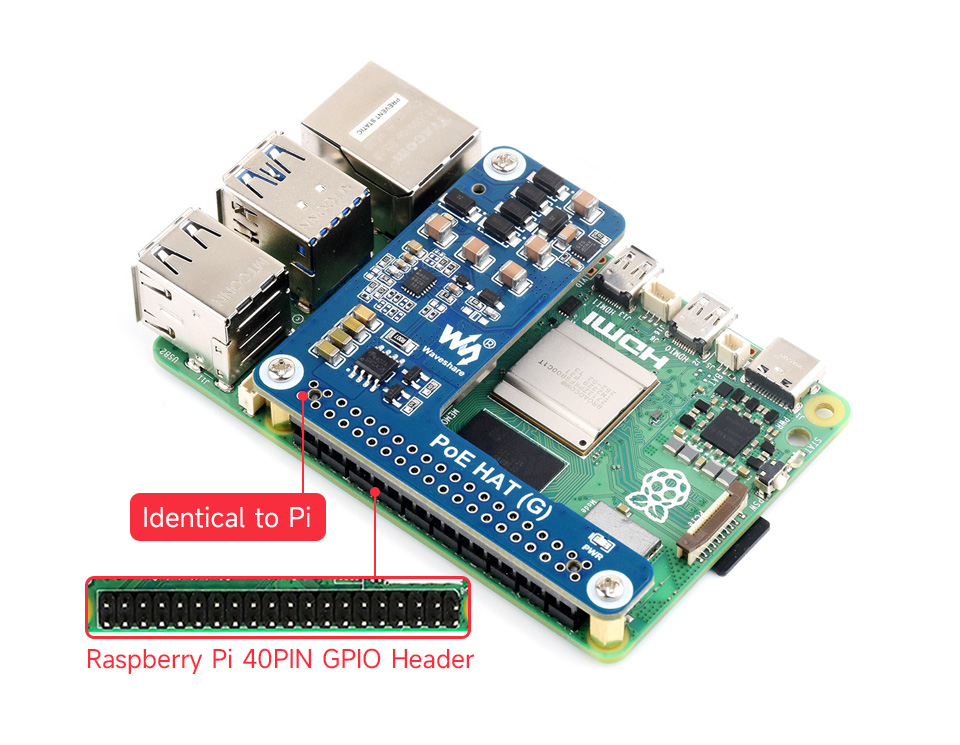
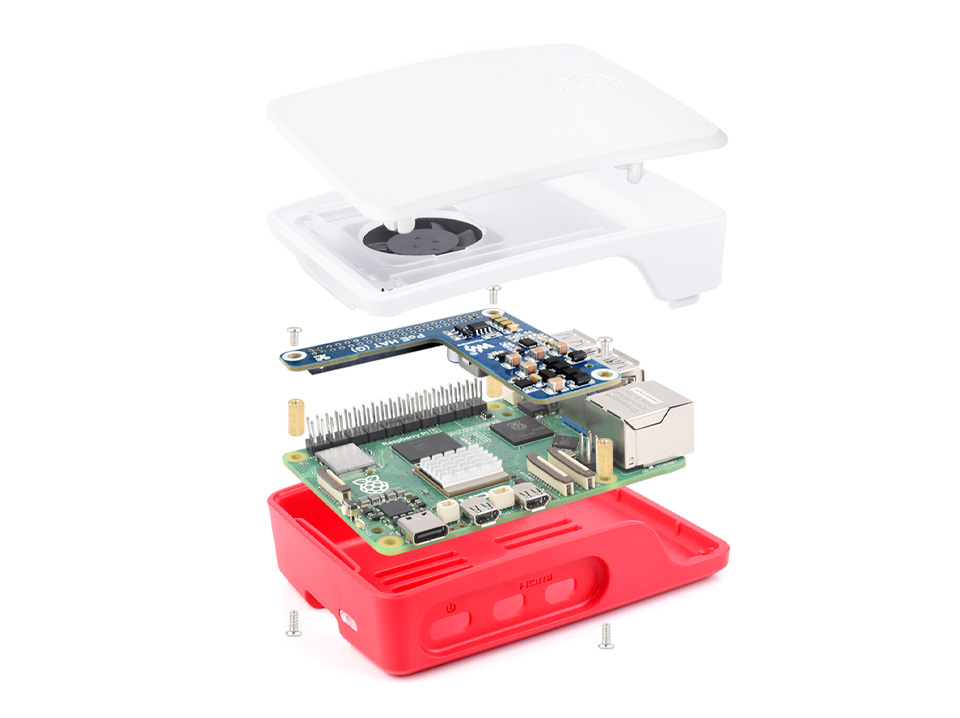
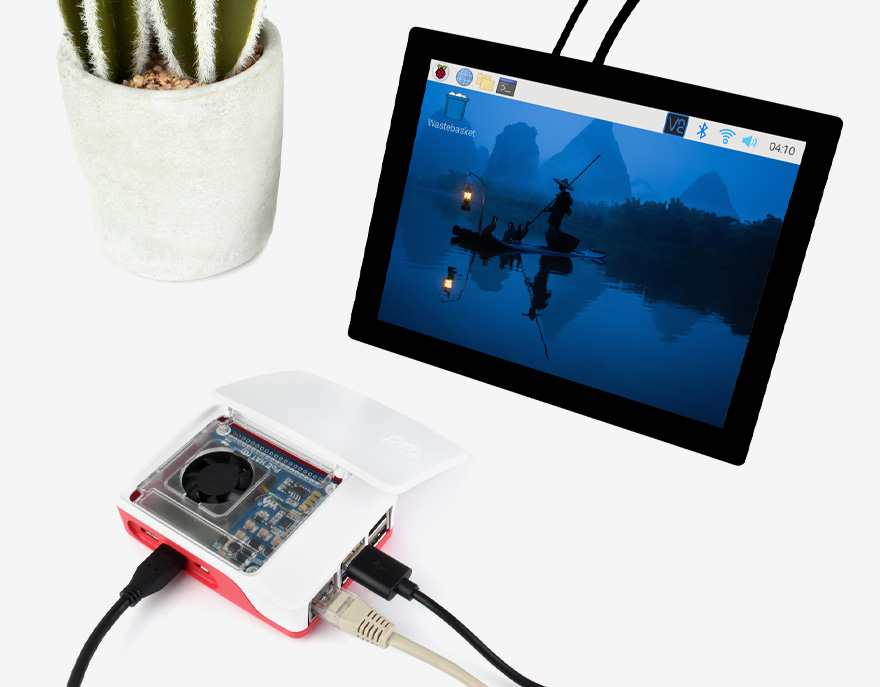
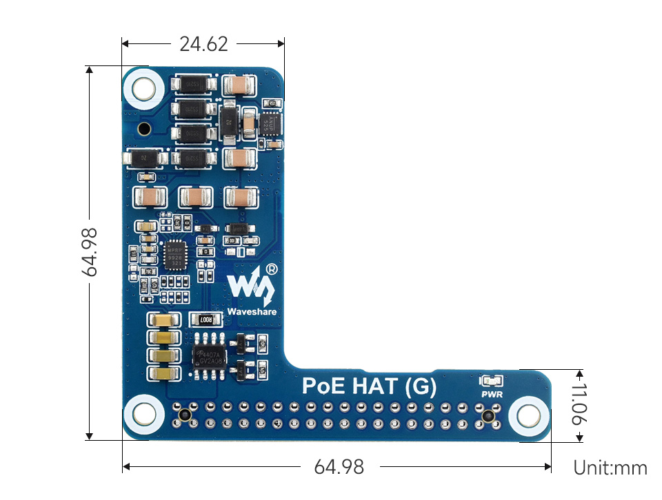
Power Over Ethernet HAT For Raspberry Pi 5, Supports IEEE 802.3af/at Network Standard
5V 5A Output, Compatible With Raspberry Pi 5 Official Case
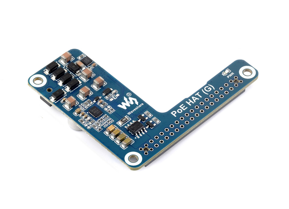
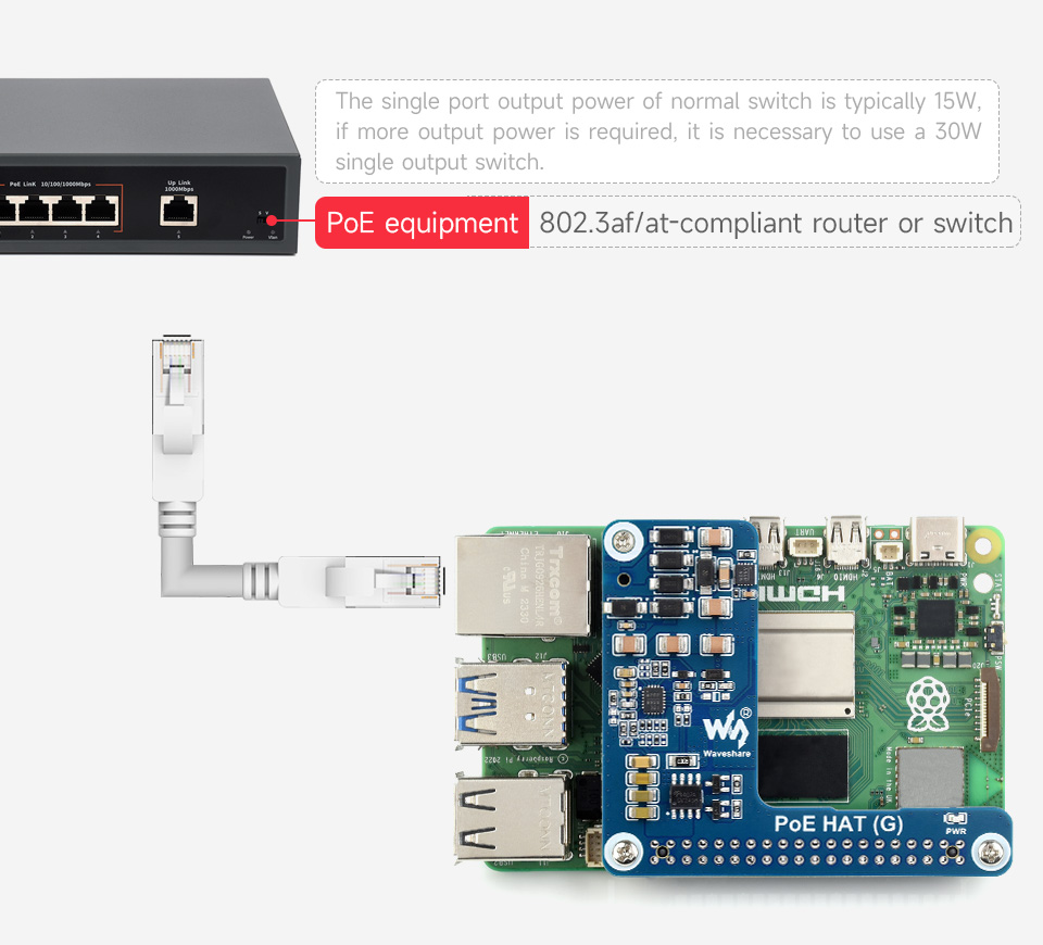
The PoE HAT (G) is an IEEE 802.3af/at-compliant PoE (Power Over Ethernet) HAT for Raspberry Pi 5. By using with a PoE router or switch that supports the IEEE 802.3af/at network standard, it is possible to provide both network connection and power supply for your Raspberry Pi in only one Ethernet cable.
- Standard Raspberry Pi 40PIN GPIO header
- PoE capability,IEEE 802.3af/at-compliant
- Onboard original IC solution for more stable PoE power performance
- Adopts non-isolated switched-mode power supply (SMPS)
- Compact and easy to assemble
| POE POWER INPUT | 38V ~ 57V DC in |
|---|---|
| POWER OUTPUT | GPIO header: 5V 5A (MAX) |
| DIMENSIONS | 56.5 × 64.98mm |
| NETWORK STANDARD | IEEE 802.3af/at PoE |
Standard Raspberry Pi 40PIN GPIO Header, Easy To Assemble Into The Official Case
Providing Both Network Connection And Power Supply For The Raspberry Pi 5 In One Cable
Compact Size Design, Can Be Directly Installed Into The Raspberry Pi 5 Case
With This Product, You Can Use An Ethernet Cable With PoE Function To Power The Raspberry Pi Directly
1 x PoE HAT (G)
1 x Standoffs pack
Resources
Wiki: www.waveshare.com/wiki/PoE_HAT_(G)